ADU-08e
Out of production
Take the ADU-11e for most cases or the ADU-10e for dedicated LF measurements.
Introduction
Performance Characteristics
The ADU-08e (Analog Digital Unit) is the core unit of the metronix multi-channel Geophysical Measurement System GMS-08. It is the result of more than 40 years of metronix´ experience in the design and manufacture of electromagnetic geophysical instruments.
The ADU-08e can be equipped with up to 6 measurement channels (5 + one internal wired). The standard configuration for wide band MT and AMT consists of 5 broad band (HF+LF combined on one board) channels. The type of channel-boards which are plugged-in will be detected by the system automatically. Multiple ADU-08e units can be connected to a network .
Each ADU can be operated as a stand-alone system, in a network using standard Local Area Network (LAN) using GigaBit Ethernet, or as part of an array, in which each unit is synchronized by its built-in GPS controlled precision clock. An access via Wireless-LAN is also possible.
The ADU-08e electronics is housed in a small (41cm x 32cm x 17cm) waterproof box only 6.5 kg in weight. In spite of the small size, it contains the complete circuitry for analog signal conditioning of up to 6 channels, 24(HF)/32(LF) Bit A/D conversion and data storage as well as a very precise GPS controlled time base (using GPS and GLONASS).
Data is stored on a removable SD card or on a USB pen drive orexternal USB hard-disk or, via the network, on the hard-disk of the connected control computer.
Either the single ADU-08e or a complete network of several ADUs can be controlled via a standard PC. This may be any (ruggedized) laptop with sufficient performance.
Each ADU can be accessed and controlled by any external PC using a standard Web-browser and aduclient software(Linux, Mac, Windows, Andoid).
All metronix magnetometers like MFS-05, MFS-06(e), MFS-07(e), FGS-02, FGS-03e, SHFT-02(e) can be connected directly to the ADU-08e. It is also possible to connect magnetometers from other companies on option.
The GMS-08 system provides a high degree of flexibility for various sensor setups. Due to its scalable and modular concept it can grow with the requirements of the user. The low number of different components also simplifies the spare part requirement.
Features
High data quality due to 24 Bit (HF) and 32 Bit (LF) Analog/Digital conversion technology
Very low system self-noise for best results in the MT “dead band”
Wide frequency range from DC to 250 kHz. Sampling rates from 256Hz up to 524kHz
System can be operated as a stand-alone or as a multi-channel network system when connecting multiple ADU-08e in a Local Area Network (LAN). An integrated W-LAN module is now standard.
ADU-08e is controlled by any Web-browser without need of further software
ADU-08e is controlled by mobile phone or tablet (adu client software)
Multiple stand-alone systems are synchronized with GPS clock accuracy.
Compatible with all metronix sensors.
Automatic unattended recording mode, pre-configured job-lists
Plug and Play recording mode if a USB stick with pre-programmed time schedule is inserted
Automatic detection of magnetometer type and automatic download of calibration function from sensor (Only for MFS-06e, MFS-07e, MFS-10e, SHFT-02e/03e, FGS-03e/04e and future sensors)
Automated system self-check of ADU-08e and sensors during set up.
Optional automatic input offset compensation eliminates self-potential of electrodes.
Real-time data processing on option (the capabilities of this feature will be further enhanced in future software releases).
12 V battery powered. Only one battery is required for each ADU-08e incl. sensors.
Compact, light-weight, ruggedized and water-protected instrument design.
Low power consumption
Wide operating temperature range from -30°C to +60°C ambient temperature.
Multiple methods such as MT, AMT, EMAP, RMT, CSAMT
Technical Data
Frequency range |
DC to 524.288 kHz |
|
Number of channels |
5 (standard) expandable to 6 |
|
Native sample rates of A/D converter |
256 Hz to 524.288 kHz selectable by power of 2 |
|
(lower sampling rates by on-line digital filtering) |
||
A/D conversion |
LF: 32 Bit (data rate max. 4,096 samples/sec) |
|
HF: 24 Bit (data rate max 262,144 samples/sec) |
||
One A/D conversion unit for each channel |
||
Input noise |
LF-ADB: 12 nV/√Hz @ 0.1 < f < 2 kHz and gain 16 |
|
Ultra low noise mode LF: 6 nV/√Hz @gain 64 |
||
HF-ADB: 13 nV/√Hz @ f >1kHz and gain 16 |
||
Input resistance |
>10 MΩ |
|
Nominal input voltage range (@ gain 1) |
switchable between +/- 1.25V and +/-10V |
|
(is done automatically by selection of sensor type) |
||
System computer |
32 bit low-power embedded controller with Linux operating system (4 CPU cores) |
|
Storage media |
32 - 512 GByte SD card (4 TB on external USB disk with ext4), USB-pen-drive or other external USB mass storage device |
|
Test facilities |
Automatic power up self-test of all important system functions including sensors and display of result on the instrument. Automatic creation of log-file |
|
Calibration |
automatic calibration |
|
Network connection |
GBit Ethernet with RJ45 connector, external WiFi module |
|
Synchronization |
72 channels GNSS synchronized clock, accuracy +/-30ns rms accuracy of 1pps signal, station position is also determined and stored (GPS, Glonass, BeiDou, Galileo) |
|
Standard connectors for 5 channel system |
1 x Network RJ45 ruggedized socket(s) |
|
3 x Magnetometer 10-pole |
||
4 x E-field input terminal 6-pole |
||
1 x GND terminal |
||
2 x input terminals for 12V battery protected against reverse polarity |
||
1 x ext. satellite antenna MCA-Type socket, |
||
2 x USB2.0 Type A |
||
Status Display |
5 lines with 64 alpha numeric characters for display of status information and direct parameter entry |
|
Case |
ruggedized, water-resistant case |
|
Weight |
appr. 6.2 kg |
|
External dimensions |
406*330*174 mm3 |
|
Power Input |
9V … 15V DC |
|
Power consumption |
5.5W – 15W |
|
depending on operation mode |
||
Operating temperature range |
-30°C to + 60°C |
The system is protected against over voltage; around 16.xx V it should switch off.
All components inside the system are industrial (-40°C .. +85°C) grade with the CPUs on the ADB and Clock/GPS even ranging up to 125°C.
Lightning protection is up to 1200V, fuses can be exchanged. Above the system will be seriously damaged
Error Messages
Component |
MainIndex |
SubIndex |
Priority |
Message |
DisplayMsg. |
Description |
MCP |
1 |
1 |
e |
meas started incompletely: invalid job file |
Start failed: Invalid job |
The new measurement job, that should be started, is erroneous. There are errors in the XML syntax or the description of the configuration of the hardware components. Please check your XML job file. |
MCP |
1 |
2 |
e |
meas started incompletely: out of memory |
Start failed: Out of memory |
There is not enough system memory available to start a new measurement. Please stop other currently running measurements before trying to restart the measurement. |
MCP |
1 |
3 |
e |
meas started incompletely: ADB sync failed |
Start failed: ADB Sync failed |
The synchronisation of the ADB boards failed. The recorded data of the single ADB channels may be out of synchronisation. This is a hardware problem. Please contact the Metronix support team. |
MCP |
1 |
4 |
e |
disk error: could not write to disk |
disk error: could not writeto disk |
The ADU-07 system, was not able to write to the CF-card or attached USB stick. This may either happen, if you renamed or deleted ATS files for an active measurement, or there is no free disk space anymore. Please note, that the data series will possibly be corrupted from the time of occurrence of this message. |
MCP |
1 |
5 |
e |
meas stopped unexpectedly: meas data error |
Unexpect. stop:Measurement data invalid |
During recording of data the last data buffers, that were received from the measurement hardware had unequal size for the different channels of the ADB boards. This may only happen, if a measurement stopped because it was either cancelled by you, it reached the “Start / Stop” fill level mark and was started in “Start / Stop mode” or it caused a buffer overflow on the SDRAM buffer on the measurement hardware. In all cases the last data buffer of the measurement (< 4 seconds of data series) may be corrupted. |
MCP |
1 |
6 |
e |
meas stopped unexpectedly: buffer full on backplane - data ok |
Unexpect. stop:Buffer full on backplane - ok |
A measurement was stopped because a buffer overflow occurred in the SDRAM buffer on the measurement hardware. This may be caused, because you made measurements with to high sampling frequency over too long time. |
MCP |
1 |
7 |
i |
stop time reached: still downloading data |
Stop time reached: Still downloading |
|
MCP |
1 |
8 |
e |
meas stopped unexpectedly: too early |
Unexpect. stop:Too early |
A measurement stopped , before it reached its desired stop time. This may not happen in normal operation and is an indication for a hardware problem. This should be examined together with the Metronix support team. |
MCP |
1 |
9 |
e |
meas stopped unexpectedly: MCP internal error |
Unexpect. stop:MCP internal error |
This message indicates a problem in the handling of the measurement data in the ADU-07 system. This shall not occur in normal operation and can not be fixed by you. Please call the Metronix support team. |
MCP |
1 |
10 |
e |
meas not started |
Start failed: Measurement notstarted |
This message says, that a measurement could not be started by the ADU-07 system. This may have different reasons. One could be, that all the channels, that are configured for the measurement, are still blocked by another measurement. Another reason could be an invalid hardware configuration fro the ADU-07 system. |
MCP |
1 |
11 |
i |
meas ended |
Meas. completedcorrectly |
This message indicates the stop of a running measurement. The measurement index of the measurement is appended to this messages. |
MCP |
1 |
12 |
i |
new meas started |
Meas. started |
This message indicated the start of a new measurement. The measurement index, that this measurement will have during its lifetime is appended to this message. |
MCP |
1 |
13 |
i |
meas timed out |
Meas. timed out |
This message is created, if not all data of the measurement was received by the CPU board, before the stop time of the measurement was reached. The ADU-07 system will try to stop this measurement and read all lasting data from the SDRAM buffer on the measurement hardware. |
MCP |
1 |
14 |
e |
system initialisation error: database |
Init error: Database error |
At start-up of the system the control program on the ADU-07 could not connect to the MySQL database. This problem could be caused by an database crash, for example if the system was switched off without shutting it down correctly. The database has to be repaired. Please contact the Metronix support team. |
MCP |
1 |
15 |
e |
system initialisation error: hardware |
Init error: Hardware error |
One of the hardware components could not be initialised correctly at start-up of the ADU-07 system. The name of the hardware component is attached to this message. Please check your hardware for errors. |
MCP |
1 |
16 |
i |
found new hardware |
This message gives you the information, that a new hardware component was detected at start-up of the system. The name of the component is attached to this message. |
|
MCP |
1 |
17 |
e |
meas data error: unequal buffer size due to hardware error |
After receiving the last samples of a measurement the size of the buffers for the different channels of a measurement are not equal. |
|
MCP |
1 |
18 |
e |
got data of idle channel |
The CPU board reads samples for a channel, that is not recording data. This points to hardware problems or invalid configuration of the ADU-07 system. If this message occurs you must to wait until the backplane SDRAM buffer is empty again, before starting a new measurement. Otherwise the measurement data of the new measurement could be corrupted by old data of the last measurement. |
|
MCP |
1 |
19 |
i |
unexpected MCP state |
This is a collective message for unexpected states in the ADU-07 control program. Please send the message with its attached information to the Metronix support team. |
|
MCP |
1 |
20 |
e |
meas started incompletely: inv. sample frequency |
One of the channels, that should take part in the new measurement should us a sampling frequency, that is not supported by the according ADB board. The ADU-07 system will choose a fallback value instead. |
|
MCP |
1 |
21 |
e |
data disk space smaller than 5MB |
Disk space low |
The free disk space on the data disk is smaller than 5 MByte. Please delete old measurement data or clear the “Error List” and “System History” to free up more disk space. |
MCP |
1 |
22 |
i |
system is booting |
Booting |
This message informs you that the ADU-07 system is currently booting up |
MCP |
1 |
23 |
i |
selftest is active |
Selftest |
This message informs you, that the ADU-07 system is currently executing selftest measurements. Attached to this message you can find the step, that is actually executed. |
MCP |
1 |
24 |
i |
system is shutting down |
Shutting down |
This message informs you, that the ADU-07 system is currently shutting down. |
MCP |
1 |
25 |
i |
system is sleeping |
Sleeping |
This message informs you, that the ADU-07 system is going into sleep mode. |
MCP |
1 |
26 |
i |
system is ready |
Idle |
This message informs you, that the ADU-07 system was completely booted up and is ready to execute the selftest procedure. |
MCP |
1 |
27 |
i |
system woke up |
Woke up from sleep |
This message informs you, that the ADU-07 system woke up from sleep mode. |
MCP |
1 |
28 |
e |
system sleep error |
Sleepmode error |
This message informs you, that an error has occurred when entering or leaving the sleep mode. |
MCP |
1 |
29 |
e |
meas started incompletely: some channels not available |
Start failed: channels not available |
This message says, that some of the channels, that should take part in the measurement are not available. This may happen, if they are either still blocked by another measurement, or if they do not support the sampling frequency, that shall be used in the measurement. |
MCP |
1 |
30 |
i |
selftest result: |
Selftest: |
This message shows you the result of the selftest procedure. If it is OK, no problems occurred during selftest. If the result is “NOK”, please examine the selftest results in the “Selftest” page of the Webinterface. At least for one of the hardware components the “Init Error” or “ADB Error” field should show a value unequal 0. You will find the according message in this table in the row, that fits to the component and Subindex you find in the “Init Error” or “ADB Error” field. |
MCP |
1 |
31 |
i |
meas cancelled by user |
Meas. cancelled |
This message informs you, that a running measurement was cancelled by the user. The measurement index of the measurement is attached to this message. |
MCP |
1 |
32 |
i |
meas stopped manually |
This message informs you, that after receiving the last samples of the measurement, the buffer were unequal of size. This happened, because you cancelled a running measurement. Please note, that the last few seconds (t < 4 seconds) of the time series are lost to avoid corruption of the measurement data. |
|
MCP |
1 |
33 |
e |
OpenMT: socket interface could not be opened/created |
This error occurs, if an OpenMT_DataInterface ProcessingObject was configured for the MCP ProcessingQueue and the socket connection could not be created/opened, using the port number that was configured in the XML job file. Maybe the port number is allready in use or there is no valid TCP/IP interface. |
|
MCP |
1 |
34 |
e |
OpenMT: socket interface could not be closed/deleted |
This error occurs, if the socket interface could not be closed. Normally this should not happen. The socket with this port number will not be available anymore until the system is rebooted. |
|
MCP |
1 |
35 |
e |
OpenMT: error while sending data via socket interface |
This error signals an problem while sending data on the socket interface to the client application. If this error occurs the data may be received incomplete at the receiver/client application. This may happen if for example the client application exits unexpectedly. |
|
MCP |
1 |
36 |
e |
OpenMT: local OpenMT client could not be started |
This error occurs if you configured the OpenMT_DataInterface in a way, that a local OpenMT client should be started. This way the data would be processed right on the local system. For some reason the client could not be started. This may happen for example, if the OpenMT executable is not located at “/mtdata/mcp_sys” or there are not enough system resources to start the client. |
|
MCP |
1 |
37 |
e |
OpenMT: local OpenMT client could not be stopped |
This error occurs, if the local OpenMT client could not be stopped at the end of the measurement. This may happen, if the OpenMT application allready exited due to some reason, or if OpenMT hang up. In this case the OpenMT process must be killed by hand before it should be started again. |
|
MCP |
1 |
38 |
i |
sleep mode activated |
The user has activated the “Sleep Mode”. The ADU-07 system will go to sleep, if this is possible. This will set the CPU board to “Suspend To RAM”. If sleeping, the system is not accessible via the Webinterface anymore. |
|
MCP |
1 |
39 |
i |
sleep mode deactivated |
The user has deactivated the “Sleep Mode”. The ADU-07 system will not go to sleep anymore. |
|
MCP |
1 |
40 |
i |
resetting sleep mode config |
The user has reset the “Sleep Mode” configuration. Therefore the “Sleep Mode” will be deactivated and furthermore all “Wake Up Periode” will be deleted. |
|
MCP |
1 |
41 |
i |
W-LAN was activated |
W-LAN was activated |
The W-Lan module was activated. |
MCP |
1 |
42 |
i |
W-LAN was deactivated |
W-LAN was deactivated |
The W-Lan module was deactivated. |
MCP |
1 |
43 |
i |
system is rebooting |
Rebooting |
The system is rebooting. |
MCP |
1 |
44 |
i |
AutoCorr: Switched Gain |
AutoCorr: Switched Gain |
The AutoCorr Processing Object switched the gain for a channel to another value than the one that was used at start-up of the job. This may happen, either because the initial gain settings have been too conservative (switch to higher gain), or because the ADB board is near to be overpowered (switch to smaller gain). |
MCP |
1 |
45 |
i |
AutoCorr: Switched DC offset correction |
AutoCorr: Switched DC offset correc- tion |
The AutoCorr Processing Object switched the DC offset corerction for a channel to another value than the one that was used at start-up of the job. This may only happen, if the DC offset of the time series reaches a value bigger/smaller than +/-400mV. In this case the ADB board is in danger to be overpowered. |
MCP |
1 |
46 |
e |
disk error: 1 or more partitions are damaged and must be repaired |
disk error: internal SD/CF card is damaged! |
The ADU-07e system detected a damaged file system on 1 or more partitions of the internal CF/SD card. Please check the CF/SD card and try to repair the disk, e.g. by re-creating the system disk, using the Metronix update tool. If this problem should occur again afterwards, the disk may have reached its End Of Lifetime and MUST be replaced! |
MCP |
1 |
47 |
e |
disk error: target disk is full - stopping jobs recording on this disk |
disk error: almost full -> stopping jobs |
The target disk is almost 100% full. The ADU-07e system is stopping all jobs that are recording data to this disk. |
MCP |
1 |
48 |
e |
disk error: no USB mass storage device mounted - using internal disk instead of |
disk error: no USB mounted using int. disk |
Data should be recorded to external USB mass storage device mounted to ADU, but no device could be found when the job was started. Maybe the USB devices was detached. Recording to internal disk now instead of external USB device. |
MCP |
1 |
49 |
e |
Ejecting TS Data SD-Card |
|
|
MCP |
1 |
50 |
e |
Inserting TS Data SD-Card |
The customer asked the ADU system to detect/insert a new TS data SD-Card. If this fails, check, if the inserted SD-Card is OK and contains a valid/supported file system, such as EXT-3, EXT-4 or FAT (including exFAT). |
|
MCP |
1 |
51 |
e |
Formating TS Data SD-Card |
The customer asked the ADU system to format the currently plugged in Frontpanel SD-Card where all TS data is stored on. All data on the SD-Card will be deleted and the SD-Card will be created with 1 single EXT4 partition. |
|
MCP |
1 |
52 |
e |
No TS Data SD-Card inserted - job will NOT be started |
There is no TS Data SD-Card plugged in on Frontpanel. The ADU system will not start the recording as there is no disk space available for the data. |
|
MCP |
1 |
53 |
e |
TS Data SD-Card failed - system will reboot |
During operation severe problems arose with the Frontpanel TS Data SD-Card. It failed and is not accessible anymore. The ADU System will reboot itself to try to go back to normal operation. Currently running jobs will be continued after reboot. If this problem occurs again, the Frontpanel TS Data SD-Card MUST be exchanged. |
|
MCP_USB |
2 |
1 |
e |
USB communication timeout |
This message advises you, that problems occurred in USB communication between the measurement hardware and the CPU board. This may either be caused by a missing USB connection between CPU board and measurement hardware or hardware problems on this components. Please check your hardware. |
|
MCP_USB |
2 |
2 |
e |
USB driver error |
This message says, that the control program has problems with connecting to the USB driver. The reasons may be the same as in the prior message. Additionally there can be problems with the Linux system. Please check your hardware. If everything is OK with the hardware, call the Metronix support team. |
|
MICRO |
3 |
1 |
e |
meas not started: hardware error |
Start failed: Hardware error |
A measurement could not be started due to problems with the measurement hardware. Please check your hardware. |
MICRO |
3 |
2 |
e |
all meas stopped: HW error - data corruption |
Unexpect. stop:HW error on backplane |
A buffer overflow occurred on the measurement hardware. Therefore all measurements are stopped. |
MICRO |
3 |
3 |
e |
Backplane SW: GPS - buffer overflow |
An internal buffer overflow occurred in the measurement hardware when accessing the GPS board. This may not happen in normal operation and points to a problem with GPS board. Pleas contact the Metronix support team. |
|
MICRO |
3 |
4 |
e |
Backplane SW: GPS - no Linefeed in GPS sentence |
This message occurs, if the data from the GPS board is corrupt. This may happen, if the GPS board is defect or not attached correctly into the slot. |
|
MICRO |
3 |
5 |
e |
Backplane SW: GPS - Timeout in interface - ignore during boot or reset of GPS |
This message occurs, if the data from the GPS board is corrupt. This may happen, if the GPS board is defect or not attached correctly into the slot. The message may occur once after start-up of the system. |
|
MICRO |
3 |
6 |
e |
Backplane SW: 5Volt supply fail |
This message says, that the 5Volt power supply on the measurement hardware failed. This is a hardware problem. The message may occur once after start-up of the system as at that time the power supply is not fully powered up. |
|
MICRO |
3 |
7 |
e |
Backplane SW: internal error |
This is a collective message for the micro controller on the measurement hardware. Please send this message with its attached information to the Metronix support team. |
|
HW_MSG |
4 |
1 |
i |
battery voltage switched to FAIR |
Battery FAIR! |
The battery voltage switched from GOOD to FAIR. Please check the battery and change it to a new one. |
HW_MSG |
4 |
2 |
e |
battery voltage switched to LOW |
Battery LOW! |
The battery voltage switched from FAIR to LOW. Battery power is now critical and the battery has to be exchanged immediately. |
HW_MSG |
4 |
3 |
e |
battery voltage critical: shutting down |
Power critical!Shutting down! |
The critical battery voltage forced the ADU-07 system to shut down. This functionality is not implemented yet. |
HW_MSG |
4 |
4 |
e |
temperature over maximum: shutting down |
Temp. critical!Shutting down! |
The internal temperature exceeded the maximum value. The system is shutting down. This functionality is not implemented yet. |
HW_MSG |
4 |
5 |
e |
temperature under minimum: shutting down |
Temp. critical!Shutting down! |
The internal temperature exceeded the minimum value. The system is shutting down. This functionality is not implemented yet. |
HW_MSG |
4 |
6 |
e |
detected BAD DATA! |
Detected BAD DATA! |
The CEA “Bad Data” Selftest Step detected bad data in one of the channels. The user should check the complete set-up for this channel (ADB Board - Cable - Sensor). It may be that either the E-Field cables have been cut, or one of the other sensor cables or sensors is broken. |
GPS_MSG |
5 |
1 |
e |
GPS board not responding |
GPS board not responding |
This functionality is not implemented yet. |
GPS_MSG |
5 |
2 |
e |
unknown GPS board |
During start-up of the ADU-07 system an invalid GPS board was found, that is not supported by the system. Please check you GPS hardware. |
|
GPS_MSG |
5 |
3 |
i |
GPS lost sync |
The ADU-07 system lost the synchronisation to the GPS signal. This means, that the state switched from “G3fix - fully synced” to a lower state. |
|
GPS_MSG |
5 |
4 |
i |
GPS gained sync |
The ADU-07 system gained a full sync to the GPS signal. If this happens, the ADU-07 system time is synchronised to the GPS time. Even if the system looses the sync afterwards, the system is still synchronised. |
|
GPS_MSG |
5 |
5 |
i |
GPS: no antenna connected |
This functionality is not implemented yet. |
|
GPS_MSG |
5 |
6 |
i |
GPS: no satellites found |
This functionality is not implemented yet. |
|
GPS_MSG |
5 |
7 |
i |
GPS: insufficient satellites for sync |
This functionality is not implemented yet. |
|
GPS_MSG |
5 |
8 |
e |
GPS: no time synchronisation |
This functionality is not implemented yet. |
|
GPS_MSG |
5 |
9 |
i |
GPS: toggled Dynamic Mode |
GPS: toggled dynamic mode now |
The Dynamic Mode of the GPS board was switched from stationary to moving, or vice versa. |
BACK_MAIN |
6 |
1 |
e |
main backplane not responding |
The main backplane board could not be initialised. Pleas check your hardware. |
|
BACK_MAIN |
6 |
2 |
e |
unknown main backplane type |
Main backplane:Unkown type |
The ADU-07 system, found an invalid main backplane board that is not supported by the system. |
BACK_MAIN |
6 |
3 |
e |
main backplane could not be booted |
The controller on the main backplane board could not be booted. This could be caused by an unknown hardware component. |
|
BACK_MAIN |
6 |
4 |
e |
status display not accessible |
This functionality is not implemented yet. |
|
SUB_BACK |
7 |
1 |
e |
sub backplane not responding |
Sub backplane: No response |
The sub backplane board could not be initialised. Please check your hardware. |
SUB_BACK |
7 |
2 |
e |
unknown sub backplane type |
Sub backplane: Unknown type |
The ADU-07 system, found an invalid sub backplane board that is not supported by the system. |
SUB_BACK |
7 |
3 |
e |
sub backplane could not be booted |
Sub backplane: Boot error |
The FPGA on the sub backplane board could not be booted. This could be caused by real hardware problems on the sub backplane board or an unknown sub backplane board. |
CAL |
8 |
1 |
e |
cal. board not responding |
CAL board: No response |
The calibration board could not be initialised. Please check your hardware. |
CAL |
8 |
2 |
e |
unknown cal. board |
CAL board: unknown type |
The ADU-07 system, found an invalid calibration board that is not supported by the system. |
ADB |
9 |
1 |
e |
ADB board not responding |
ADB board: No response |
The ADB board could not be initialised. Please check your hardware. |
ADB |
9 |
1 |
e |
unknown ADB type |
The ADU-07 system, found an invalid ADB board that is not supported by the system. |
|
ADB |
9 |
2 |
e |
invalid ADB configuration |
During the configuration phase for a new measurement the ADB board should be started with a configuration, that is not supported by this ADB board. The measurement will be started using fallback values. The changed configuration is attached to this message. Please check your measurement configuration. |
|
ADB |
9 |
3 |
e |
ADU07-ADB-LF: internal DC offset failure |
The internal DC offset on the ADB board is too high and can not be corrected. This points to a hardware problem with the ADB board in this channel. Please check the hardware for errors. |
|
ADB |
9 |
4 |
e |
ADU07-ADB-LF: internal gain correction error |
The internal gain correction on the ADB board failed and is out of range. This points to a hardware problem with the ADB board in this channel. Please check the hardware for errors. |
|
ADB |
9 |
5 |
e |
ADU07-ADB-LF: gain out of range 1:1 |
The gain for combination “gain stage 1 = 1”, “gain stage 2 = 1” is out of range. This points to a hardware problem. Please check the selftest results for this step. |
|
ADB |
9 |
6 |
e |
ADU07-ADB-LF: gain out of range 8:8 |
The gain for combination “gain stage 1 = 8”, “gain stage 2 = 8” is out of range. This points to a hardware problem. Please check the selftest results for this step. |
|
ADB |
9 |
7 |
e |
ADU07-ADB-LF: gain out of range 1:64 |
The gain for combination “gain stage 1 = 1”, “gain stage 2 = 64” is out of range. This points to a hardware problem. Please check the selftest results for this step. |
|
ADB |
9 |
8 |
e |
ADU07-ADB-LF: gain out of range 64:1 |
The gain for combination “gain stage 1 = 64”, “gain stage 2 = 1” is out of range. This points to a hardware problem. Please check the selftest results for this step. |
|
ADB |
9 |
9 |
e |
ADU07-ADB-LF: external offset correction error |
The external offset correction on the LF ADB board failed. This points to hardware problems with the offset correction DAC on the ADB board. Please check the hardware. |
|
ADB |
9 |
10 |
e |
ADU07-ADB-LF/MF: 4Hz low pass filter error |
The attenuation of the 4 Hz low pass filter on the LF/MF ADB board is out of range. This points to hardware problems with the 4 Hz LP filter on the ADB board. Please check the hardware. |
|
ADB |
9 |
11 |
e |
ADU07-ADB-LF: noise out of range |
The noise on the sensor input is out of range. Please activate the 4 Hz low pass filter for noise reduction, if possible and check the sensor connection. |
|
ADB |
9 |
12 |
e |
ADU07-ADB-LF: DC level too high for gain |
ADB: DC level too high |
The DC level on the sensor input is too high for a amplification. Therefore do not use the gain stages other then 1:1. Otherwise the input signal will exceed the maximum dynamic range of the channel and the measurement data will be useless. |
ADB |
9 |
13 |
e |
ADU07-ADB-HF: internal DC offset failure |
The internal DC offset on the ADB board is too high and can not be corrected. This points to a hardware problem with the ADB board in this channel. Please check the hardware for errors. |
|
ADB |
9 |
14 |
e |
ADU07-ADB-HF: internal gain correction error |
The internal gain correction on the ADB board failed and is out of range. This points to a hardware problem with the ADB board in this channel. Please check the hardware for errors. |
|
ADB |
9 |
15 |
e |
ADU07-ADB-HF: gain out of range 1:1 |
The gain for combination “gain stage 1 = 1”, “gain stage 2 = 1” is out of range. This points to a hardware problem. Please check the selftest results for this step. |
|
ADB |
9 |
16 |
e |
ADU07-ADB-HF: gain out of range 8:8 |
The gain for combination “gain stage 1 = 8”, “gain stage 2 = 8” is out of range. This points to a hardware problem. Please check the selftest results for this step. |
|
ADB |
9 |
17 |
e |
ADU07-ADB-HF: gain out of range 1:64 |
The gain for combination “gain stage 1 = 1”, “gain stage 2 = 64” is out of range. This points to a hardware problem. Please check the selftest results for this step. |
|
ADB |
9 |
18 |
e |
ADU07-ADB-HF: gain out of range 64:1 |
The gain for combination “gain stage 1 = 64”, “gain stage 2 = 1” is out of range. This points to a hardware problem. Please check the selftest results for this step. |
|
ADB |
9 |
19 |
e |
ADU07-ADB-HF: 1Hz high pass filter error |
The attenuation of the 1 Hz high pass filter on the LF ADB board is out of range. This points to hardware problems with the 1 Hz HP filter on the ADB board. Please check the hardware. |
|
ADB |
9 |
20 |
e |
ADU07-ADB-HF: noise out of range |
The noise on the sensor input is out of range. Please check the sensor connection. |
|
ADB |
9 |
21 |
e |
ADU07-ADB-HF: DC level too high for gain |
ADB: DC level too high |
The DC level on the sensor input is too high for a amplification. Therefore do not use the gain stages other then 1:1. Otherwise the input signal will exceed the maximum dynamic range of the channel and the measurement data will be useless. |
ADB |
9 |
22 |
e |
ADU07-ADB-COMMON: sync failed |
ADB: sync error |
The synchronisation of the single ADB boards before a measurement failed. Therefore the single channels of the measurement may jitter by the t = 1/Sample Frequency. This points to a hardware problem. Please check the ADB board for errors. |
ADB |
9 |
23 |
e |
ADU07-ADB-MF: 500Hz high pass filter error |
The attenuation of the 500 Hz high pass filter on the MF ADB board is out of range. This points to hardware problems with the 500 Hz HP filter on the ADB board. Please check the hardware. |
|
ADB |
9 |
24 |
e |
ADU07-ADB-MF: gain out of range 4:16 (LF) |
The gain for combination “gain stage 1 = 4”, “gain stage 2 = 16” is out of range on the LF input circuitry for the ADU07-ADB-MF board. This points to a hardware problem. Please check the selftest results for this step. |
|
ADB |
9 |
25 |
e |
ADU07-ADB-MF: gain out of range 16:4 (LF) |
The gain for combination “gain stage 1 = 16”, “gain stage 2 = 4” is out of range on the LF input circuitry for the ADU07-ADB-MF board. This points to a hardware problem. Please check the selftest results for this step. |
|
ADB |
9 |
26 |
e |
ADU07-ADB-MF: gain out of range 4:16 (HF) |
The gain for combination “gain stage 1 = 4”, “gain stage 2 = 16” is out of range on the HF input circuitry for the ADU07-ADB-MF board. This points to a hardware problem. Please check the selftest results for this step. |
|
ADB |
9 |
27 |
e |
ADU07-ADB-MF: gain out of range 16:4 (HF) |
The gain for combination “gain stage 1 = 16”, “gain stage 2 = 4” is out of range on the HF input circuitry for the ADU07-ADB-MF board. This points to a hardware problem. Please check the selftest results for this step. |
|
ADB |
9 |
28 |
e |
ADU07-ADB: Gain Correction factors out of date -> updated now |
ADB: Gain Corr Out Of Date updated now! |
The Gain Correction factors that are stored inisde the ADB EEPROMs is out of date. A re-calibration of the Gain Stages should be done by executing the according selftest steps. |
ADB |
9 |
29 |
e |
ADU07-ADB: Gain Correction factors are invalid. Using Defaults (1.0). |
ADB: Gain Corr Invalid |
The Gain Correction factors that are stored inside the ADB EEPROMs are invalid (either because the Cal File is damaged or the File does not fit to the ADB Board type). In either case the Gain Stages need to be re-calibrated executing the according selftest steps. In the meantime all correction factors will be set to 1.0. |
ADB |
9 |
30 |
e |
ADU07-ADB: Calibration of Gain Stages failed |
ADB: Calibra tion of Gain Stages failed |
The Calibration of the Gain Stages failed. The Gain Correction factors are propably invalid now. The Calibration should be re-started. If it fails again a HW problem occured. |
ADB |
9 |
31 |
e |
ADU07-ADB: Gain Correction factor out of tolerance window |
ADB: Gain Corr.Factor Out Of Range |
The determined Gain Correction factor for a certain Gain Stage is out of range. This points to a HW error on the ADB board. |
ADB |
9 |
32 |
e |
ADU07-ADB: Unknown error in Gain Stage calibration |
ADB: Gain Corr Invalid |
An unknown error occured during the calibration of the gain stage. This should not happen. Nothing can be done by the user. |
ADB |
9 |
33 |
e |
Unified Fast Selftest cannot be executed on MF board. |
ADB: Unified Fast Selftest does not work on ADU07-ADB-MF |
The Unified Fast Selftest does not work on the ADU07-ADB-MF board. Please use another selftest mode. |
ADB |
9 |
34 |
e |
Detection of LF LSB failed |
ADB: Detection of LF LSB failed |
The detetcion of the LF LSB failed. This points to a hardware problem, either with the ADB board, or the Calibration part of the Clock/GPS board. |
ADB |
9 |
35 |
e |
Detection of HF LSB failed |
ADB: Detection of HF LSB failed |
The detetcion of the HF LSB failed. This points to a hardware problem, either with the ADB board, or the Calibration part of the Clock/GPS board. |
ADB |
9 |
36 |
e |
probe resistance out of range - check electrode and cable |
ADB: probe re- sistance out ofrange |
The detetcion of the probe resistance failed. Check the E-Field cable or E-Field probe. |
ADB |
9 |
37 |
e |
Magnetic Field sensor check failed - check sensor and cable |
ADB: Check of Magnetic field sensor failed |
The check of the magnetic field sensor failed. It shows wrong phase / amplitude values. Please check the connected Magnetic Field sensor ans sensor cable. |
ADB |
9 |
38 |
e |
Gain Stage amplification on ADB is out of range - hardware error |
ADB: Gain Stage out of range |
The gain amplification for the Gain Stage on the ADB board is out of range. This points to an hardware problem, either with the ADB board or the calibration board. |
ADB |
9 |
39 |
e |
Input Divider do not work correctly - hardware error |
ADB: Input Divider error |
The Input Divider that configure the ADB board to work as E-Field or H-Field channel, do not work correctly. This points to a problem with the ADB board (hardware error). |
ADB |
9 |
40 |
e |
Radio Filter do not work correctly - hardware error |
ADB: Radio Filter error |
The Radio Filter on the ADB board to not work correctly. This is caused by a hardware error on the ADB board. As a result the recorded time series may be overpowered, if you record data in high noise environment (e.g. close to radio transmitters, power lines, …). |
ADB |
9 |
41 |
e |
Probe Resistance is too high - check electrode and cable |
ADB: Probe Re- sistance too high |
The Probe Resistance that has been detected during selftest is too high. This points to either a broken E-Field cable or a broken probe. The E-Field probe and cable for the according channel should be checked, unless the measurement is done on very resitive ground. |
ADB |
9 |
42 |
e |
Probe Resistance big anisotropy between Ex and Ey - check elecrode and cable |
ADB: Probe Re- sistance big anisotropy |
There is a big anisotropy in Probe Resistance between Ex and Ey channels. Unless the measurement takes place ground with very different resistance values for Ex and Ey the electrodes and cables should be checked. Likely they are broken for either Ex or Ey or one of the directions has bad connection to the ground. |
GPS_STATUS |
10 |
1 |
i |
GPS Status report |
This message shows a GPS status report. |
|
HW_STATUS |
11 |
1 |
i |
HW status report |
This message shows a hardware status report containing the actual battery voltage, current and status and other values. |
|
GLOBAL |
12 |
1 |
e |
unknown system identity |
GLOBAL: unknownsystem info |
This message says, that the measurement contains an invalid system identity, that is not supported by the ADU-07 system. Please check your hardware. |
USB_AUTOMOUNTER |
13 |
1 |
i |
USB: scanning device |
USB: scanning device |
This message says, that a new USB mass storage device was attached and is scanned by the USB Automounter. The USB Automounter will try to mount the device to ist target directory and start any job-lists, if configured. |
USB_AUTOMOUNTER |
13 |
2 |
i |
USB: mounting device |
USB: mounting device |
The device is mounted to the configured target directory. |
USB_AUTOMOUNTER |
13 |
3 |
i |
USB: submitting job |
USB: submittingjob |
The job of the job-list was submitted to the ADU-07(e) internal job table. |
USB_AUTOMOUNTER |
13 |
4 |
e |
USB: mounting of device failed ! |
USB: mounting of device failed |
It was tried to mount the device to ist target directory, what failed. Maybe the configured target directory inside the “ADU07Conf” XML file is invalid. Please check the configuration file. |
USB_AUTOMOUNTER |
13 |
5 |
e |
USB: start of job failed |
USB: starting of job failed |
It was tried to start the XML job. This failed. The reason may be that there is no valid XML job file at the location specifed in the ADU07Conf XML file. |
USB_AUTOMOUNTER |
13 |
6 |
e |
USB: scanning of device failed |
USB: scanning device failed |
The newly attached USB device was tried to be scanned by the USB Automounter. This failed. The reason can be that there was no preconfigured directory strutcture or now valid ADU07Conf XML file. |
USB_AUTOMOUNTER |
13 |
7 |
i |
USB: device was detached |
USB: device wasdetached |
An attached USB device was detached again. |
USB_AUTOMOUNTER |
13 |
8 |
i |
USB: job-list transferred completely |
USB: job-list transferred completely |
All jobs of an job-list from an USB device have been transferred completely to the “jobs” table. |
USB_AUTOMOUNTER |
13 |
9 |
i |
USB: script was executed correctly |
USB: script executed correctly |
A script of the script-list inside the ADU07Conf XML file was executed correctly. |
USB_AUTOMOUNTER |
13 |
10 |
i |
USB: execution of script failed |
USB: script execution failed |
The execution of a script defined inside the ADU07Conf XML file failed. Check the script that should be started. |
USB_AUTOMOUNTER |
13 |
11 |
i |
USB: script-list executed completely |
USB: scipt-listexecuted completely |
All scripts of the script-list have been executed. |
CON |
14 |
1 |
i |
connector not responding |
Connector boardNo response |
The connector board could not be initialised. Please check your hardware. If you have an ADU-07 system with old, revision 1.0 connector board this is no problem (Revision 2.0 available since ADU-07e). |
CON |
14 |
2 |
e |
unknown connector type |
Connector boardUnknown type |
The ADU-07 system, found an invalid connector board that is not supported by the system. |
CON |
14 |
3 |
e |
failed to configure sensor input dividers |
Connector boardFailed to set input dividers |
When starting a measurement the ADU-07e system failed to correctly configure the sensor input dividers. This probably is a hardware error on the Connector Board. As a result the sensor input dividers may either be set to 1 or 8 with may result in a time series amplitude beeing to high or low (depending on the sensor type). |
SENSOR |
15 |
1 |
i |
no plug and play sensor found |
Sensor: No PNP sensor found |
The sensor on the specific input could not be initialised. Please check your hardware. If you there is no MFS-06e, MFS-07e or EFD-07e sensor connected, this is no problem. |
SENSOR |
15 |
2 |
e |
unknown sensor type |
Sensor: Unknown type |
The ADU-07 system, found an invalid connector board that is not supported by the system. |
SENSOR |
15 |
3 |
i |
invalid XML cal file |
Sensor: invalid XML CALfile |
The ADU-07 system, found an new, intelligent sensor but was unable to read the sensors XML cal file from it. This may either be caused ba the XML cal file beeing broken, or by the sensor having no XML cal file stored inside ist EEPROM at all. This is cirtical. The sensor will operate properly. If you want to recalibrate the sensor, please contact the Metronix support team. |
SENSOR |
15 |
4 |
i |
read XML cal file from sensor |
Sensor: read CAL file |
The ADU-07 system, found an new, intelligent sensor and successfully read a XML cal file from ist internal EEPROM. The file is stored inside the local database and will be used for all further measurements along with this sensor. |
USER |
16 |
1 |
i |
user msg.: |
User MSG: |
This is a user specific message. It is not created by the ADU-07 system, but by the customer who configured the system. |
PWR_STAGE |
17 |
1 |
i |
power stage not responding |
Power Stage No response |
The connected Power Stage (ARS2000 drive) could not be detected during boot-up of the system. |
PWR_STAGE |
17 |
2 |
e |
unknown power stage type |
Power Stage Unknown type |
During boot-up of the system a Power Stage was detected, but its type information is invalid. |
PWR_STAGE |
17 |
3 |
e |
Power Stage error: check manual - |
Power Stage error: |
Internal error of the Power Stage has occured. Check the TXM-22 manual for a detailed description of the error. |
PWR_STAGE |
17 |
4 |
i |
Cleared Power Stage error: |
Cleared Power Stage error: |
An active error of the Power Stage was cleared. |
PWR_STAGE |
17 |
5 |
e |
Undervoltage Power Stage: check power supply |
Undervoltage Power Stage |
During operation the DC link voltage of the connected Power Stage drop beneath the minimum value. Please check the power supply for the Power Stage. |
PWR_STAGE |
17 |
6 |
e |
Overvoltage Power Stage: check braking resistor and operation mode |
Overvoltage Power Stage |
During operation the DC link voltage of the connected Power Stage exceeded the maximum value. Please check the braking resistor and the operation mode (output frequency and current). |
PWR_STAGE |
17 |
7 |
e |
Overtemperature Power Stage: check cooling |
OvertemperaturePower Stage |
During operation the Power Stage temperature exceeded the maximum value. Please check the cooling of the Power Stage. |
PWR_STAGE |
17 |
8 |
e |
Short Ciurcuit in Power Stage: check electrodes and cables |
Short Circuit Power Stage |
The output of the Power Stage is short circuited. Please check the electrode and cables. |
PWR_STAGE |
17 |
9 |
e |
Overload of Power Stage: check operation mode |
Overload Power Stage |
The Power Stage was overloaded. Please check your operation mode and if needed, reduce the output current. |
PWR_STAGE |
17 |
10 |
e |
Failed to load DC link of Power Stage |
Failed to load DC link of Power Stage |
The DC link of the Power Stage cannot be loaded. Please check the braking resistor and power supply. |
PWR_STAGE |
17 |
11 |
e |
Failed to reset Power Stage |
Failed to resetPower Stage |
The reset of the Power Stage failed. Check the communication interface to the Power Stage (cables). |
PWR_STAGE |
17 |
12 |
e |
Failed to acknowledge error in Power Stage |
Failed to ack. errors in PowerStage |
The acknowledge of errors inside the Power Stage failed. Check the communication interface to the Power Stage (cables). |
PWR_STAGE |
17 |
13 |
e |
Failed to enable Power Stage |
Failed to enab.Power Stage |
The Power Stage can not be enabled. Check power supply and hardware enable signals. |
PWR_STAGE |
17 |
14 |
e |
Failed to disable Power Stage |
Failed to disable Power Stage |
The Power Stage can not be disabled. This is a serious problem. Check the communication cables. |
PWR_STAGE |
17 |
15 |
i |
Detecting electrode coupling |
Detecting Elec trode Coupling |
The TXM-22 started to detect the electrode coupling. |
PWR_STAGE |
17 |
16 |
e |
Failed to detect the electrode coupling |
Failed to de tect Electrode Coupling |
The Power Stage failed to detect the electrode coupling. As a result no signal can be fed into the ground in a correct manner. Please check the electrode coupling. |
PWR_STAGE |
17 |
17 |
e |
Emergency Shutdown Active |
Emergency Shut down Active |
An Emergency Shutdown occured. The Power Stage was switched off therefore. Please check the Power Stage condition and find out the reason for the Emergency Shutdown. Afterwards release the Emergency Switch. |
PWR_STAGE |
17 |
18 |
i |
Emergency Shutdown was Cleared |
Emergency Shut down was clear ed |
The Emergency Shutdown cleared. The Power Stage is ready for operation again. |
PWR_STAGE |
17 |
19 |
e |
Lost Connection to Power Stage |
Lost Connect tion to Power Stage |
The Connection to the Power Stage was lost. No communication can be done between TXB-22 and TXM-22 anymore. Please check the cabling between the two devices. |
PWR_STAGE |
17 |
20 |
i |
Reconnected to Power Stage |
Reconnected to Power Stage |
The connection to the Power Stage was established again. The system is now working correctly again. |
PWR_STAGE |
17 |
21 |
i |
Power Stage Output was enabled |
Power Stage Output was enabled |
The Power Stage Output was enabled and is now outputting signal waveforms. |
PWR_STAGE |
17 |
22 |
i |
Power Stage Output was disabled |
Power Stage Output was disabled |
The Power Stage Output was disabled and is not outputting signal waveforms, even if a job is running. The output current is hardly set to 0. |
PWR_STAGE |
17 |
23 |
e |
Sequence Config Error: Base Frequency is 0Hz |
Seqc. Config Error: Base Frequency = 0Hz |
The configured Sequence is invalid. The base frequency for the output signal was set to 0Hz. This is no valid value. The execution of the Sequence (Joblist) will be stopped. |
PWR_STAGE |
17 |
24 |
e |
Sequence Config Error: Rotation Frequency is 0Hz |
Seqc. Config Error: RotationFrequency = 0Hz |
The configured Sequence is invalid. The “Rotating Dipole” or “Alternating Dipole” functionality is active AND the rotation frequency is set to 0Hz. The joblist will be started, but before a output signal is generated, the error must be acknowledged. The output signals current dipole will not be rotated or alternated. |
PWR_STAGE |
17 |
25 |
e |
General Config Error: Invalid Operation mode |
General Config Error: Invalid Operation Mode |
The configured Sequence is invalid. An invalid operation mode was configured. E.g. in the current version the “HF” mode is not available. The joblist will be started in LF mode instead with the fastest possible output signal frequency. |
PWR_STAGE |
17 |
26 |
e |
Invalid FW Version: TXM-22 Operation stopped |
Invalid FW Ver sion: Operationstopped |
When initialising the ARS2000 (TXM-22 Power Stage) and invalid or not supported FW version was detected inside the Power Stage. For security meanings the operation of the TXM-22 system was stopped. No jobs can be started. Check the Power Stage FW version on the “Hardware Config” page of the User Interface and ask Metronix for support. |
PWR_STAGE |
17 |
27 |
i |
Testfirmware was found inside Power Stage |
Test FW Versionwas found in Power Stage |
A Test FW version was found inside the connected TXM-22 Power Stage. This should only occur in prototypes. As the FW version is marked as Test FW and therefore as untested undefined behaviour may occur. Please inform Metronix of this issue. If Metronix says the FW can be used, this message can be ignored. Otherwhise a FW update with the lates released FW should be done. |
GSM |
18 |
1 |
e |
invalid phone number |
GSM: invalid phone number |
When trying to sent a new status SMS the configured phone number was invalid. As a result the SMS was not sent to the recipient. |
GSM |
18 |
2 |
i |
Sending new status SMS |
A new status SMS was sent. |
|
GSM |
18 |
3 |
i |
Communication error with GSM modem |
A communication error with the GSM modem occured. |
ADB error 37:
can also be caused by to hight external magnetic fields. The 4Hz al signal is added to the external field and causes overflow.
The other reason is that is the cal signal returns an invalid value.
In this case the communication between pre-amplifier and cal may be distorted; pre-amplifier may be changed.
Overview
The ADU-08e comes in a waterproof, ruggedized Peli case housing.
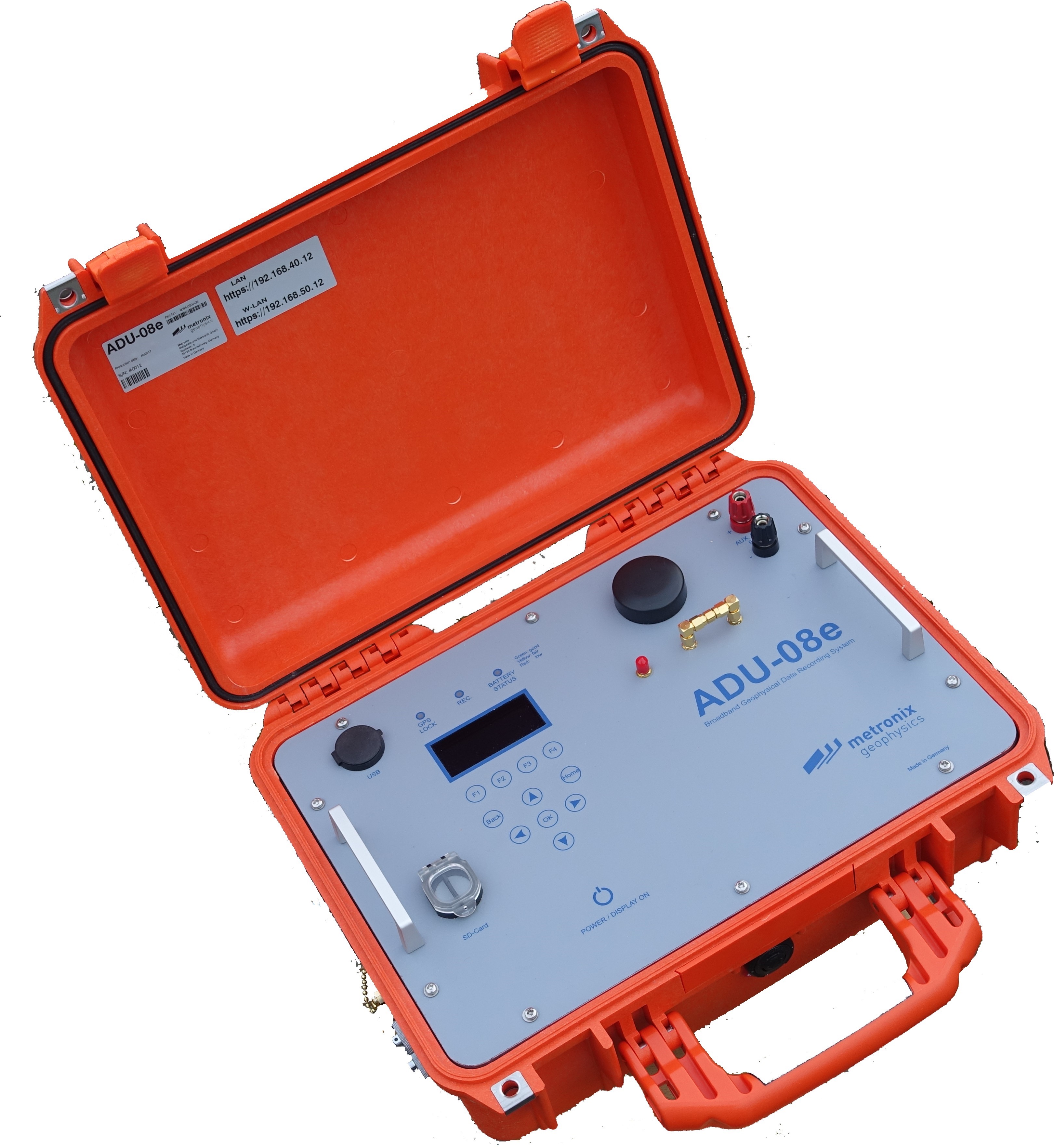
The ADU-08e is delivered along with an additional external GPS-antenna and two battery cables.
Figure 3 2 and 2-3 show the ADU-08e and its operating elements. All operating elements are numbered and described in more detail in the following pages.
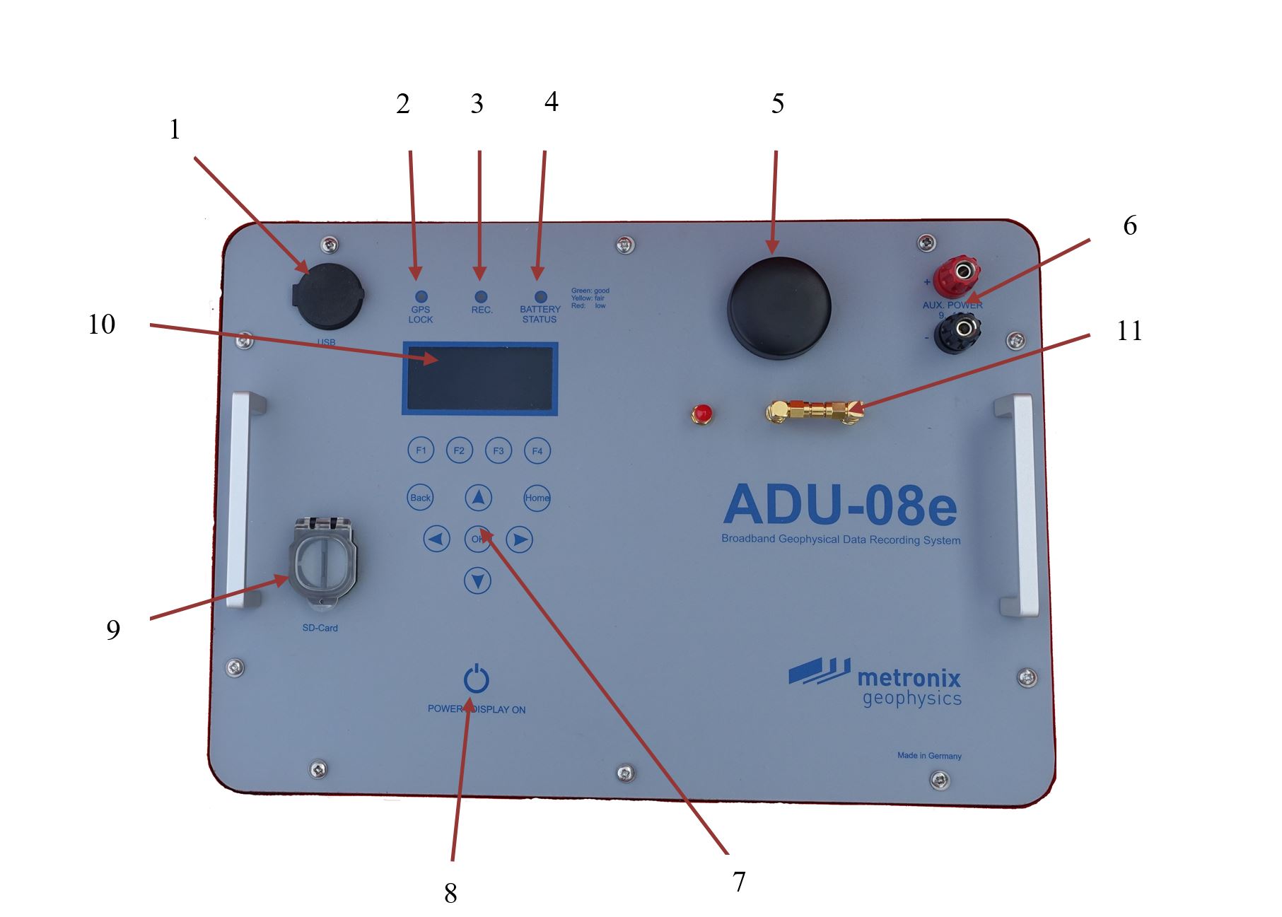
Operating elements of ADU-08e front-panel
USB Socket
GPS Status LED
Recording Status LED
Battery Status LED
GPS antenna
Binding posts for auxiliary power supply
Key pad
On/Off button
Slot for SD card
Display
Bridge for internal or external GPS Antenna, left is external, right is internal antenna (as shown in the picture)
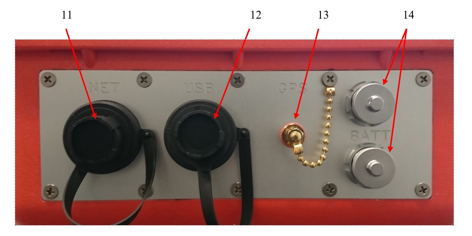
Operating elements of ADU-08e left side
Network socket
USB socket
GPS antenna socket
Battery sockets
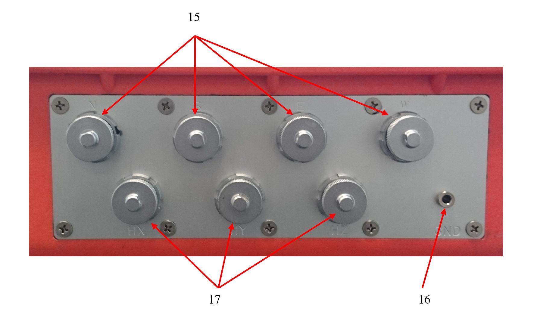
Operating elements of ADU-08e right side
E-field connectors
GND socket
Magnetometer connectors
USB Type “A” Connectors
You will find one USB Type A connector on the front lid and another one on the left side for connection of USB mass storage devices or USB WiFi stick. Mass-storage devices and WiFi sticks will be recognized by the operating system automatically.
GPS status LED
This LED shows 3 states:

|
LED off |
No GPS synchronization or system in clock hold mode. |

|
LED blink |
System has detected sufficient number of satellites, but has not reached the maximum accuracy yet. |

|
LED steady green |
GPS locked and system fully synchronized. |
If the LED is not illuminated despite the GPS-antenna is corrected properly, it may be that the antenna does not have an open view to the sky allowing the system to detect at least 4 satellites in track. In this case it may be helpful to look for another location for the antenna.
If the ADU has been transferred to another location which is far away from the last one with a valid GPS lock (more than 300 km), it can take a while until the system has found a sufficient number of satellites. In this case the stored Almanac of the satellite positions is no more valid for the new location and has to be updated first. This procedure can take up to 15 minutes.
It also may take a longer time if a long time span (more than 1 week) has been passed since the last GPS fix.
Recording status LED
The red LED is switched on if a data acquisition is running.
Battery Status LED
In order to get a quick check of the battery voltage without a laptop connected, this LED is provided. The meaning of the different colors is:

|
Battery good (voltage higher than 12.0V, fully charged) |

|
Battery voltage fair (<12.0V and >10.5V) |

|
Battery low (voltage < 10.5 and > 10.0V) shutdown will come soon. |

|
The system has shut down and closed all running jobs automatically. |
The exact battery voltage and current are also shown on the status display and it is monitored in the log file. If the battery voltage gets low, the ADU will shut-down automatically.
GPS Antenna
The built-in GPS antenna receives the signals from the satellites. It needs to have view to the open sky. In case the built-in antenna is used, the ADU may not be installed in a metal box.
Binding Posts for Auxiliary Power Supply
Here a 9 to 15V power source can be connected in order to power the ADU-08e.
Slot for SD card
Here an SD card can be inserted. It is used for data storage and can have a size up to 200 GByte presently. The size delivered on standard is 32 GByte.
Alpha Numerical System Status Display
The display shows the status of the system after self-test and many other important parameters and information. The display is switched off automatically after a period of 30 seconds in case no button is pushed. In order to switch it on again you need to press the “On” button (8).
Battery Connectors
The ADU-08e is equipped with 2 battery sockets. You can connect a 12V battery or two batteries in parallel for extended operation time. Before the delivered battery cable can be connected, you have to remove the protection cap of the socket. The input voltage is 12 V nominal; the allowed voltage spans from 10.5V to max. 16V.
The inputs are protected against wrong polarity and over and under voltage. If the ADU should not work, check for wrong polarity or wrong voltage. If the instrument shall be operated without interruption, you may use the second battery input to connect a fresh battery. After having it connected, you may disconnect the old battery from the ADU-08e for recharging. An auxiliary 3rd battery input is provided on the front-panel. Here for instance a small Gel- or Li-Ion battery can be connected in order to provide a continuous power-supply when the system is transported to the next site. It may especially be helpful when the distance between two sites is only a few hundred meters as it could be the case in small scale AMT or RMT surveys.
Antenna socket for external GPS antenna
The ADU comes with a built-in GPS antenna which is sufficient for most cases. We also deliver a second external antenna which may be used in difficult reception situations or when the ADU is housed in a metal case. In this case the cable bridge has to be plug into position EXT.
Socket for Network
The network cable is connected to this socket (RJ45 type).
USB socket
A USB device such as USB key or WLAN key can be connected here.
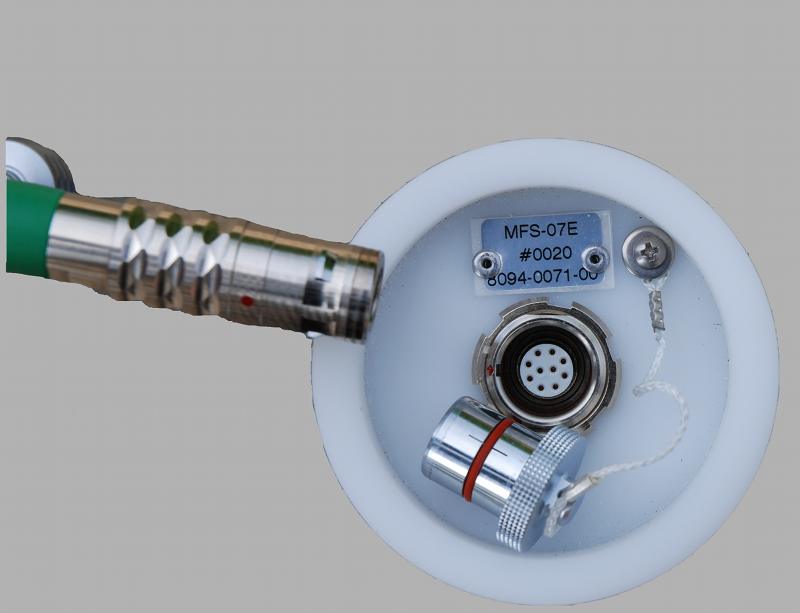
E-field connectors for standard and buffered E-field cable
These four terminals are used to connect the standard or the buffered E-field cables. The plugs on the E-field cable have 6 pins. The center pin 6 is the pin where the standard E-field cable has to be connected to. In a typical arrangement the ADU is located in the center of the two E-field lines. Plug-in the cable connector in a way that the red dots match on plug and socket and push the plug in until it clicks.
Socket 6-pole ODU MiniSnap G32KON-T06QP00-000 Pin |
Signal |
1 |
+12V |
2 |
-12V |
3 |
Sensor GND |
4 |
Sensor GND |
5 |
n.c. |
6 |
Input (+ or -) |
.jpg)
Pinning of E-Field socket (front view)
GND Socket
This socket is used to connect the grounding rod or electrode with the ADU. The grounding can be done by a steel rod or an electrode. Grounding should be done closely to the ADU.
Caution
Grounding of the ADU is very important as otherwise the inputs can float and may be saturated.
Connector for Magnetic Field Sensors
On the right side of the ADU-08e you will find 3 sockets (10-pole ODU K-series) to connect the magnetic field sensor cables. Plug-in the cable connector in a way that the red dots match on plug and socket and push the plug in until it clicks.
Socket 10-pole ODU MiniSnap G32K0C-P10QJ00-0000 Pin |
Signal |
1 |
+12V |
2 |
-12V |
3 |
H-Chop |
4 |
Sensor GND |
5 |
Cal Signal+ |
6 |
Cal Signal - |
7 |
Input + |
8 |
Input - |
9 |
\(I^{2}C\) SDA |
10 |
\(I^{2}C\) SCL |
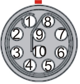
Pinning of H-Field socket (front view)
Installation in the Field
This chapter describes the setup of the ADU-08e and ADU-08e-2C and of the sensors in the field.
Definition of Polarities
The following polarities are defined in the ADU-08e-2C:
E-Fields
EX: |
NORTH = Plus |
South = Minus |
|
EY: |
East = Plus |
West = Minus |
When applying a DC voltage to the input terminals of the ADU-08e / ADU-08e-2C as described above, the result will be a positive output on the A/D converter. The time series will show a positive value.
Standard Setup
Necessary Components
Only a few components are required:
ADU-08e (9094-0004-05) and /or ADU-08e-2C DataLogger (Metronix Art.No. 9094-0005-02) |
|
|
4 electric field probes (EFP-06) (Metronix Art.No. 8094-0012) |
|
|
4 electric field cables (Metronix Art.No. 8094-0040-00) |
|
|
3 magnetic field cables (Metronix Art.No. 8094-0038-20) (5 channel setup) |
|
|
3 magnetic sensors MFS or fluxgate / SHFT (5 channel setup) |
|
|
1 grounding rod + cable or grounding electrode |
|
|
Control computer, mobile phone or tablet computer for system control |
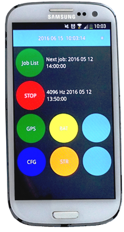
|

|
Placement of Sensors in the Field
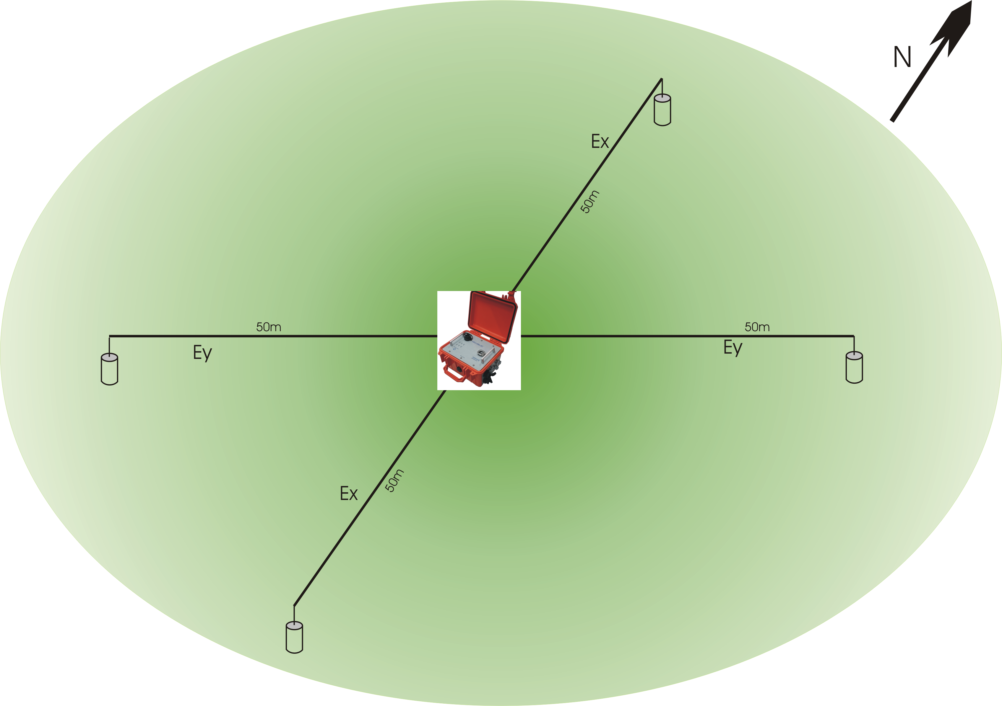
Typical field setup 2 channels
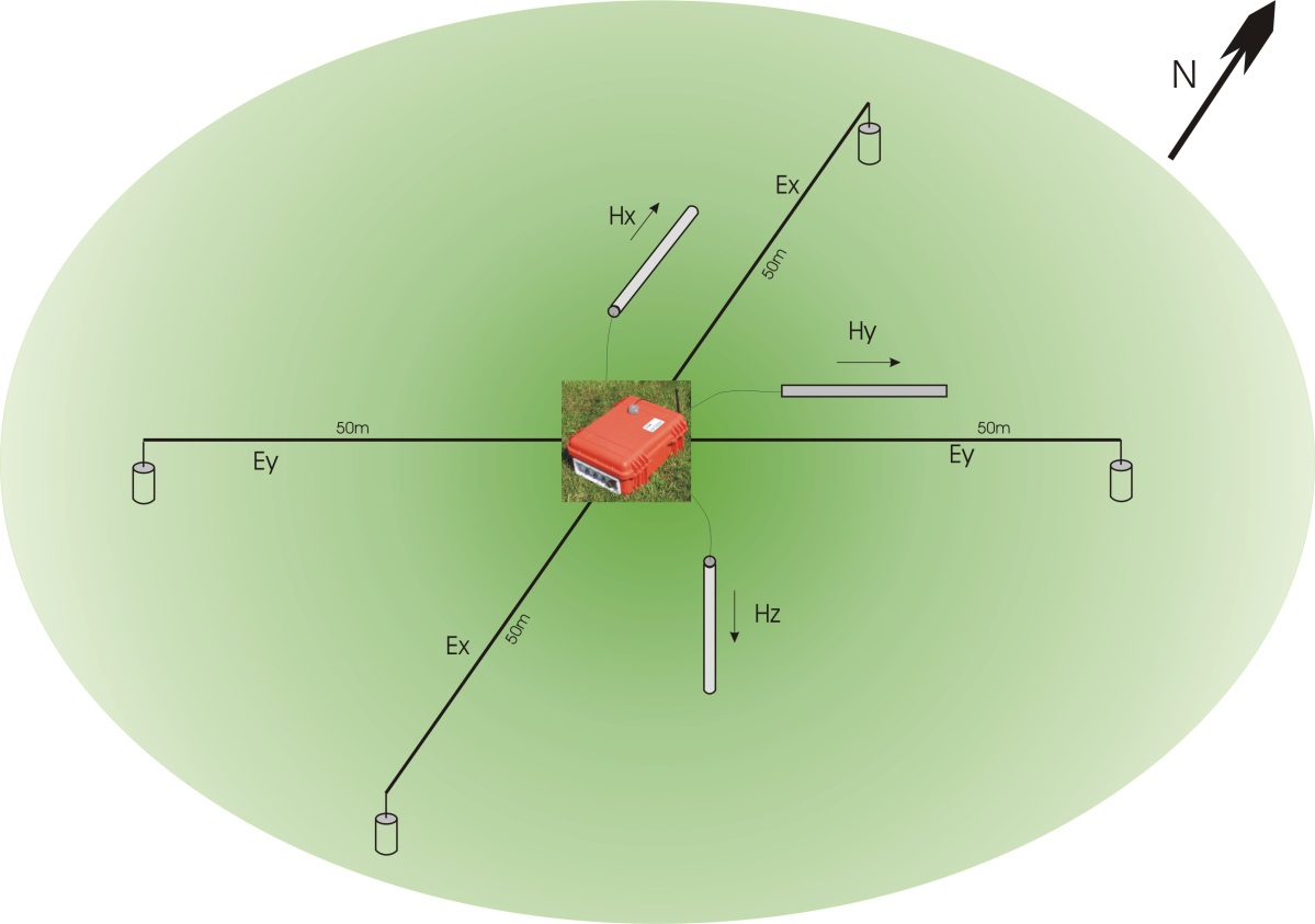
Typical field setup 5 channels
It is recommended to align the field setup to the north. This means:
Ex is heading to the north/south direction (connectors N and S on ADU-08e / ADU-08e-2C).
Ey is heading to the east/west direction (connectors E and W of ADU-08e / ADU-08e-2C).
Ground electrode or steel rod should be placed close to the ADU-08e / ADU-08e-2C system.
Hx is pointing North (cable end South), 5 channel setup with ADU-08
Hy is pointing East (cable end West), 5 channel setup with ADU-08
Hz is pointing down (cable end up), 5 channel setup with ADU-08; Hz can be skipped in case (no tipper in this case)
Caution
Swapping the connectors (e.g. North/South for Ex) will invert the recorded time series and finally mess up the measurement results.
Note that this issue can be fixed afterwards by inverting the time series before data processing is done.
Caution
Mixing E-Field channel connectors (e.g. using North/West for Ex and South/East for Ey) will completely mix up the recorded time series.
Such time series cannot be repaired anymore!
Caution
Rotated Setups (sensors not orientated North-South, East-West) can lead to later problems when using third party interpretation software.
Set-up of Electrodes
In the standard MT field setup the orthogonal electric fields EX and EY are recorded. For the measurement of one electric field component two electrodes (such as EFP-06) are used. They are dug into the soil with a distance of approx. 80 to 100 m. In order to have an optimum common mode rejection of disturbing radio transmitters, the ADU-08e / ADU-08e-2C should be located in the center of the electric field dipoles.
Note
A long(er) dipole gives you some noise-free amplification of the electric field signals.
If an L-shape setup cannot be avoided you should use 4 probes in any case. The electrodes close to the ADU may NOT be connected with the ground electrode because this would induce a higher noise into the electric field inputs.
The exact alignment of the probe’s location must be determined using a compass and a measuring tape. The distance of the N/S and E/W dipole has to be noted and must be entered in the setup menu later on. The probe location can be marked by pickets to find them faster in the field again.
Dig holes of 20 cm to 30 cm depth and plant the probe into the soil after having added some water. Make sure that the bottom of the probe has a good contact with the soil and cover the probes by soil completely. It is important that the soil is pressed down finally in order to obtain a good contact. It also may help to improve the ground resistance by mixing a paste of water and soil and planting the probe into that paste.
In case the soil is very dry, the grounding resistance can be diminished using some Bentonite which is mixed with soil around the probes and by adding some water. The Bentonite will keep the moisture for a longer period of time. If you need to do long term measurements in a dry area, the probes should be dug in deeper (>80cm).
The typical probe resistance ranges between a few hundred Ohms up to 10 kOhms. However, it might be much higher in very resistive areas such as deserts and arid areas etc. In this case the use of the optional buffered cables is required especially for higher frequency recordings. Please also make sure that the E-field cables are not positioned too close to the magnetometers (>1m).
Note
If the probes are not used, make sure that the sponge at the bottom of the protection case is wet by water and that its lid is closed. The cap can also be sealed by some adhesive tape if the probe is not used for a longer period of time. The free cable end should be left outside the protection case in order to avoid corrosion on its open end.
Note
The condition of the electrodes can be checked as follows: take a new, fresh electrode and one of the electrodes which are already in use. Put them on a wet cloth or a container filled with some water on its bottom and check the voltage offset between both electrodes. The voltage should be less than 30mV. If it is much higher the old electrode must be replaced.
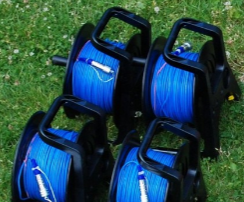
The cable that comes out of the electrode is connected to the E-Field cable reel.
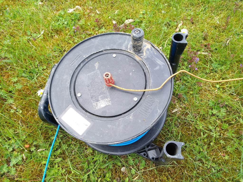
Finally, the E-Field connector of the cable reel is connected to the E-Field inputs of the ADU-08e / ADU-08e-2C data logger (N, S, E or W).
Note
After some time of usage the cable coming out of the EFP-06 electrode starts to corrode. Make sure to clean the end of the cable before connecting it to the cable roll to make good contact.
Note
Make sure the EFP-06 electrode has good connection to the ground. In very dry areas use Bentonite additionally in order to increase the conductivity between electrode and ground.
Caution
Bad contact between electrode and soil will cause increased noise in your E-Field data. This is most likely detected by big probe resistance values for the E-Field channels during the instrument´s self-test.
Caution
The EFP-06 are Lead/Lead-Chloride electrodes. Take care to wear proper protection gloves or wash hands after handling with it. Do not eat or drink during installation of the EFP-06 electrodes.
Note
Collect electrode waste separately:
The waste electrodes must be collected separately from other (for example municipal) waste and handed over to competent organization for treatment, recycling, etc.
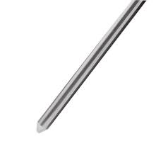
Set-up of Grounding Electrode or Steel Rod
Place the grounding electrode (or steel rod) close to the ADU-08e / ADU-08e-2C system and connect it to the “Sensor Ground” input of the ADU-08e / ADU-08e-2C system.
Caution
Make sure that the sensor ground has good contact to the earth. Bad contacts for sensor ground may cause floating sensor signals and increased noise inside the time series data.
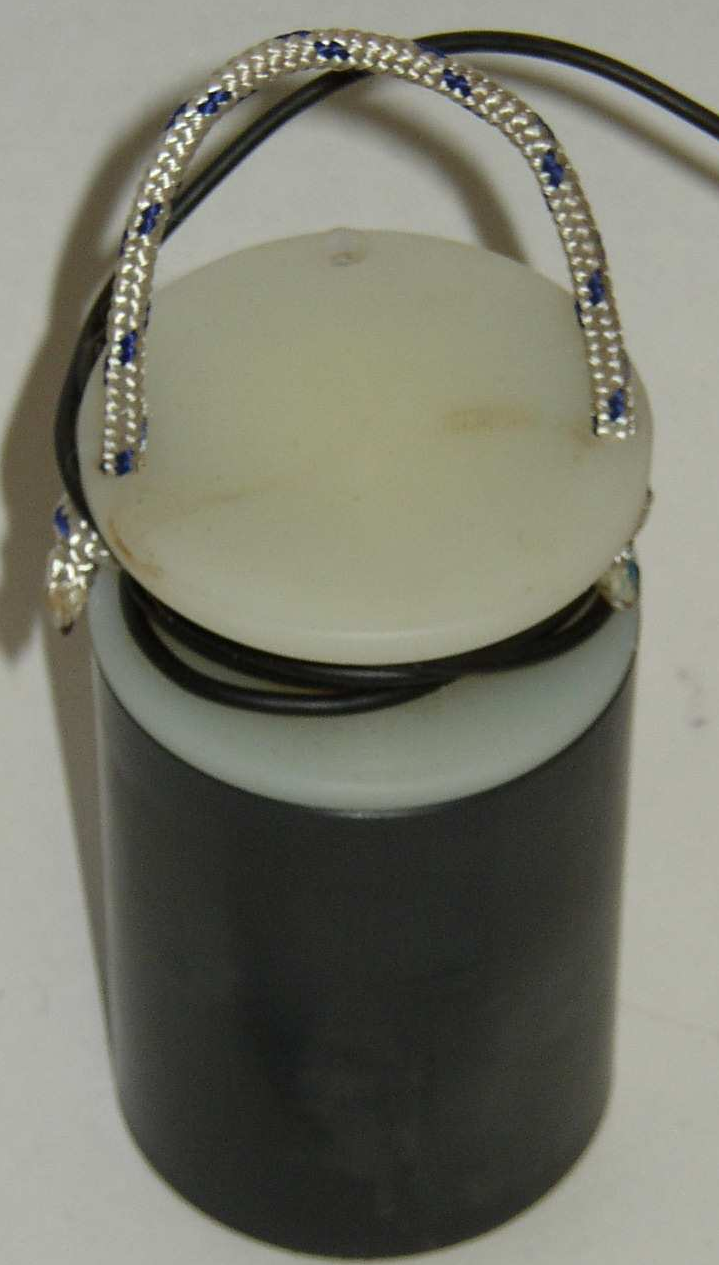
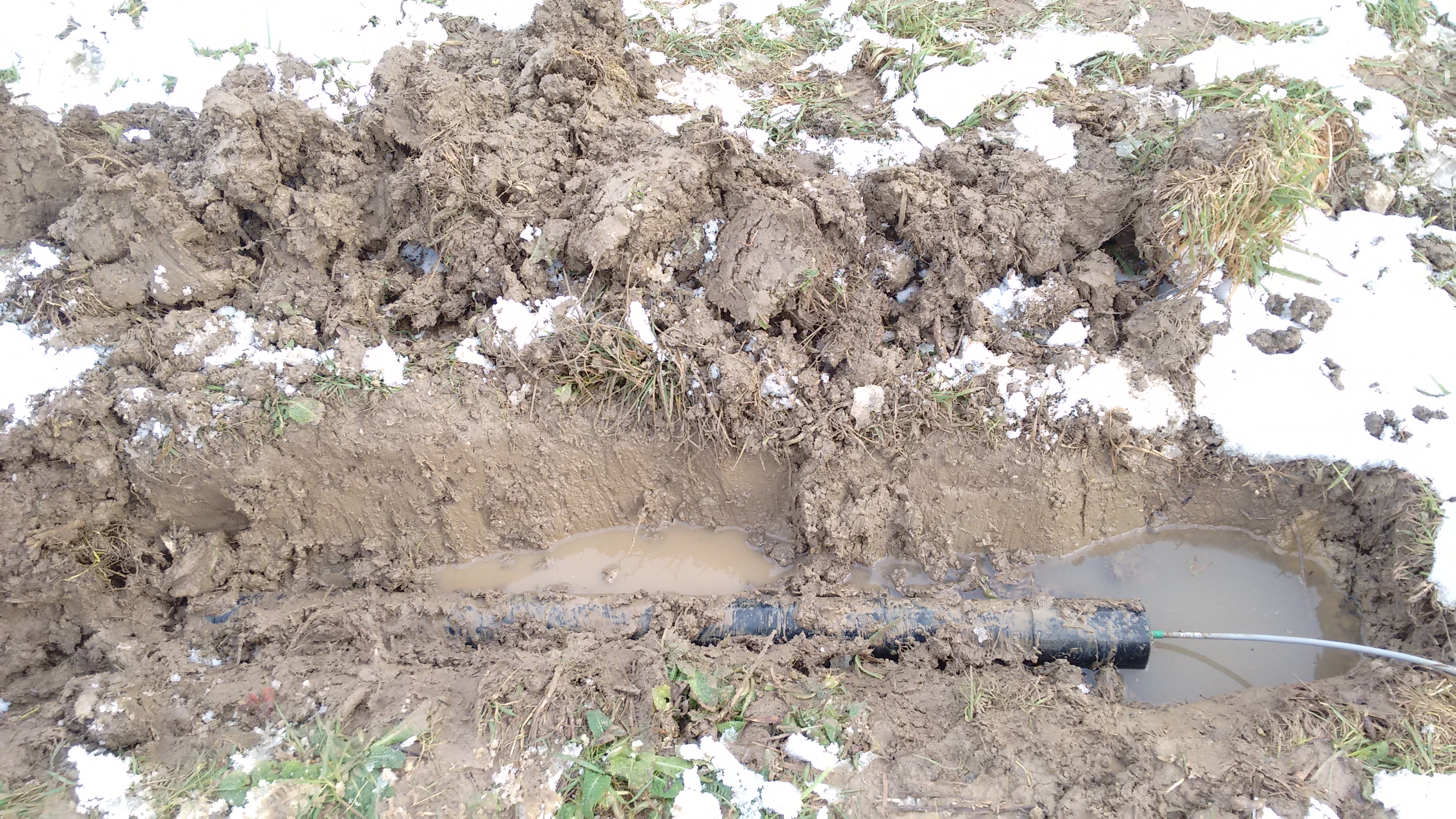
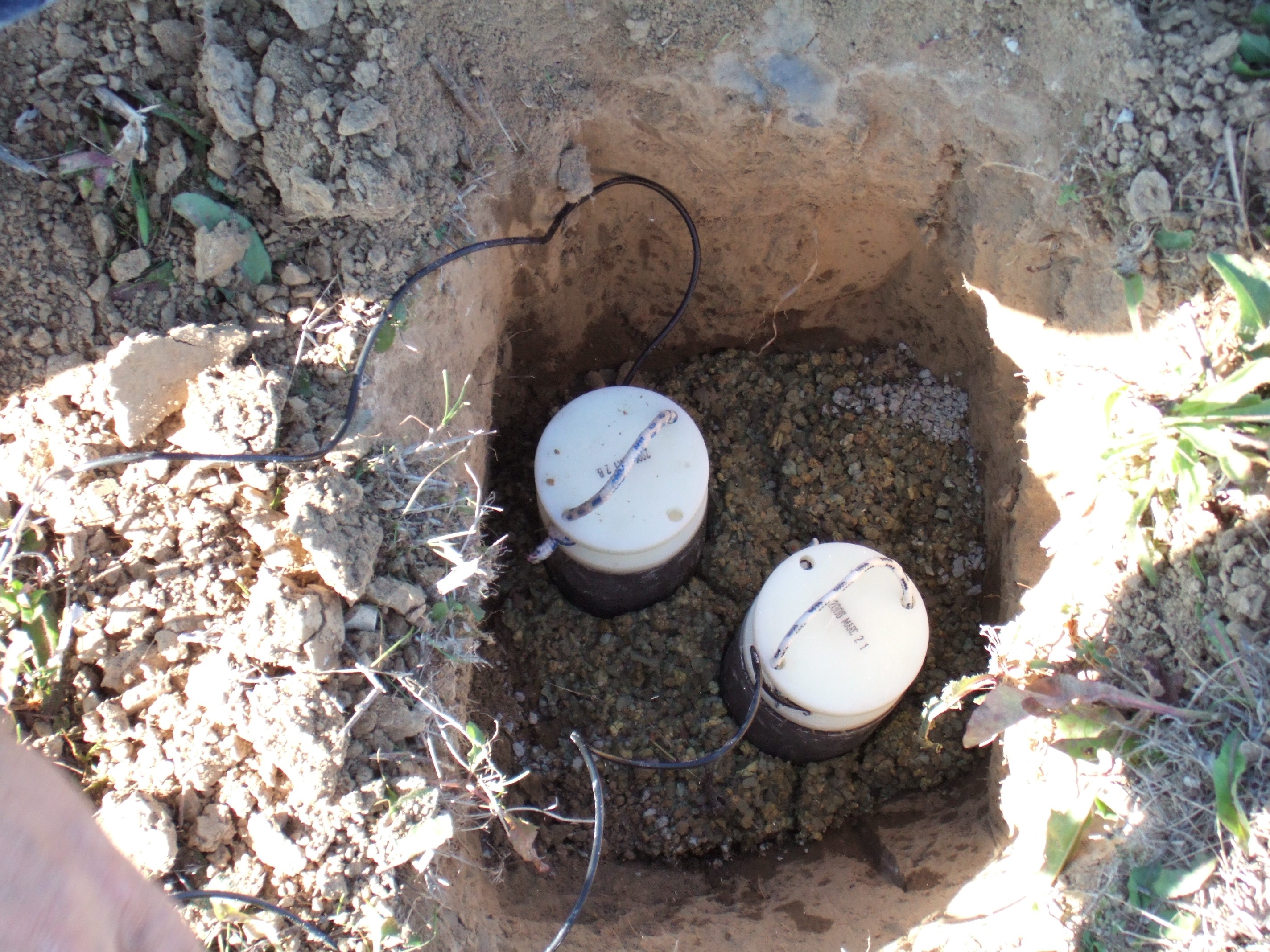
Set-up of Coils
By default the coils are connected by a 20m cable; the distance to the ADU-08e is necessary to avoid interference, especially when you work with the ADU and connect a cable or change the battery.
Caution
When you walk beside the coil the soil will vibrate and your measurement is destroyed.
Same applies when using the mobile phone.
Dig a trench at least 30cm deep - oriented North and oriented East; drill a hole as deep as the coil length. The coils must be placed exactly horizontal an vertical (+/- 2 degrees is ok realistically).
Note
Use geographical orientation - not magnetic. Finally you want to plot your data on a map, which are all geographical North orientated.
The MFS coils are not temperature sensitive. The fluxgate is; here you get more stable data if you dig deeper.
Make sure that the cables are not moving in the wind.
Note
The setup spawns a 3D space and all components must be perpendicular.
Set-up of GPS Antenna
The GPS antenna is connected to the “GPS” input of the ADU-08e / ADU-08e-2C. The antenna itself must be placed somewhere with clear view to the sky and should be protected against strong movement by wind.
Note
If time synchronous data shall be recorded, e.g. for means of remote reference data processing it is most important to provide full GPS synchronisation at any time of the recording.
Note
Note that the ADU-08e / ADU-08e-2C res-syncs to GPS only, if the system is NOT recording data. Therefore make sure that the ADU-08e / ADU-08e-2C is fully synced to GPS before the measurement is started.
Boot Up ADU-08e / ADU-08e-2C
When all other components have been installed and connected to the ADU-08e / ADU-08e-2C, the last step is to connect it to a 12V battery. This may be any 12V battery with sufficient capacity (>10Ah). The delivered battery cable is connected to one of the two sockets labeled as „BAT“. Connect the black clamp with the –pole and the red clamp with the +pole of the battery.
Note
A connection with wrong polarity on each of the battery inputs which has been accidentally made will not cause any harm on the instrument.
It will then just simply not start working. After a correct battery connection it will boot up normally.
When the battery has been connected, the ADU-08e / ADU-08e-2C can be switched on by pressing the “Power” button on its front panel.
The ADU-08e / ADU-08e-2C will boot-up and execute the “Self-test” routine. The “Self-test” ends as soon as the “GPS” and “Battery” LEDs on the ADU-08e / ADU-08e-2C Front-panel stop blinking.
Connection of The Field Laptop Computer
The laptop is connected to the ADU-08e / ADU-08e-2C with a network cable or by a WiFi connection in case a supported WiFi stick is inserted and has been activated. A suitable WiFi stick is delivered along with the instrument. As a network cable you may use any standard Cat5e or better network cable with RJ45 plugs. One end of this cable is connected to the socket labeled „NET“, the other end is connected to the Ethernet socket of the laptop computer.
If the communication is ok and after having entered the proper network address which is written on the sticker inside the front cover into your browser you will be able to contact the ADU-08e / ADU-08e-2C. We recommend to book-mark the ADU´s address in your browser.
Note
Make sure that no Proxy Server is selected in your browser settings! The network parameters of your laptop have to be set in a way that it can access the 192.168.60.xxx network address room for LAN access. The number xxx ranges from 0 to 255 and must be different from the last address number of the ADU.
Please refer to chapter 4.2.8.2 for the necessary setup.
Note
Note that the total length of the network cable between ADU and Laptop may not exceed 100m.
Note
Note that for means of power saving the ADU-08e / ADU-08e-2C will deactivate the WiFi after 15 minutes if no device has been connected. You can reactivate WiFi with help of the power button.
Note
Note that your Laptop needs to have a network interface that is configured to work inside the same network segment as the ADU-08e / ADU-08e-2C system.
As the LAN interface of the ADU-08e / ADU-08e-2C does not provide a DHCP server (it does not configure the network card of your laptop automatically, if being connected), this needs to be done manually.
If you connect via WiFi, the network interface of your Laptop is configured by the ADU-08e / ADU-08e-2C automatically.
A detailed description of how to communicate with the ADU is given in the chapters 5,6 and 7.
Manual Configuration of LAN Network Interface
The LAN network interface that shall connect to the ADU-08e / ADU-08e-2C must work within the same network address range as the ADU-08e / ADU-08e-2C does. As the ADU-08e / ADU-08e-2C default LAN IP address is within the 192.168.60.XXX range, your Laptop network interface must be configured to an address in the 192.168.60.XXX range, too.
Example for Windows 10:
|
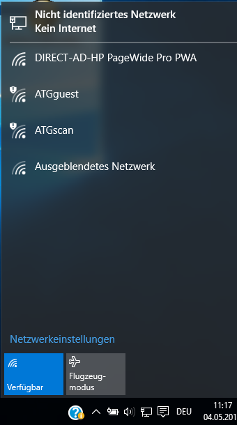
|
|
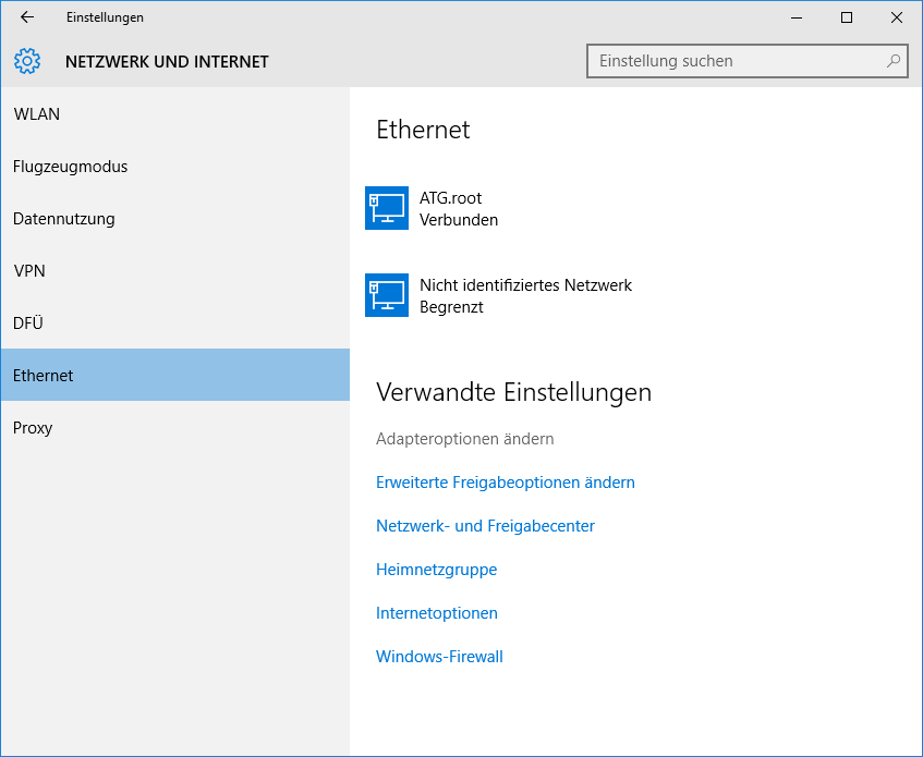
|
|
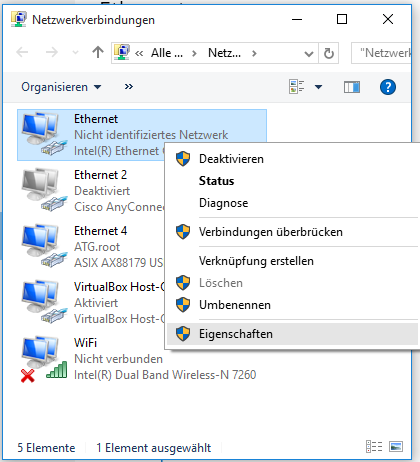
|
|
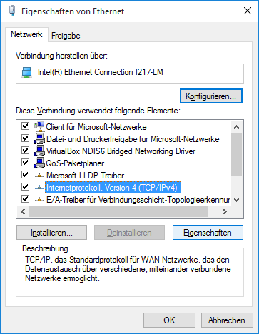
|
|
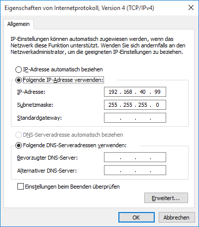
|
See also connecting to the ADU in troubleshooting section.
Check the connection, using the “ping” Tool:
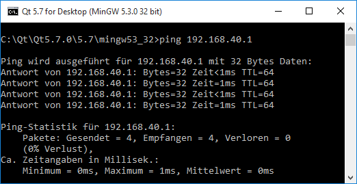
If successful, the number of lost packets is 0 (0%). If the connection cannot be created the number of lost packets is 4 (100%)
Pre-Measurement Checks
Once the ADU-08e / ADU-08e-2C has booted up and the self-test has finished (indicated by GPS and Battery LEDs stop blinking), the following checks need to be performed:
Check on front panel that GPS and STATUS LED are green.
Check that the Battery LED is also green or at least yellow.
Check Self-test Results
The self-test results need to be checked, too. In most cases they will be OK. In case of warnings or critical errors the self-test results MUST be checked before the start of the measurement. This can be done in the following ways:
Mobile App “ADUCLIENT”:
1.) Check “STR” Button on Main Menu If the buttons |
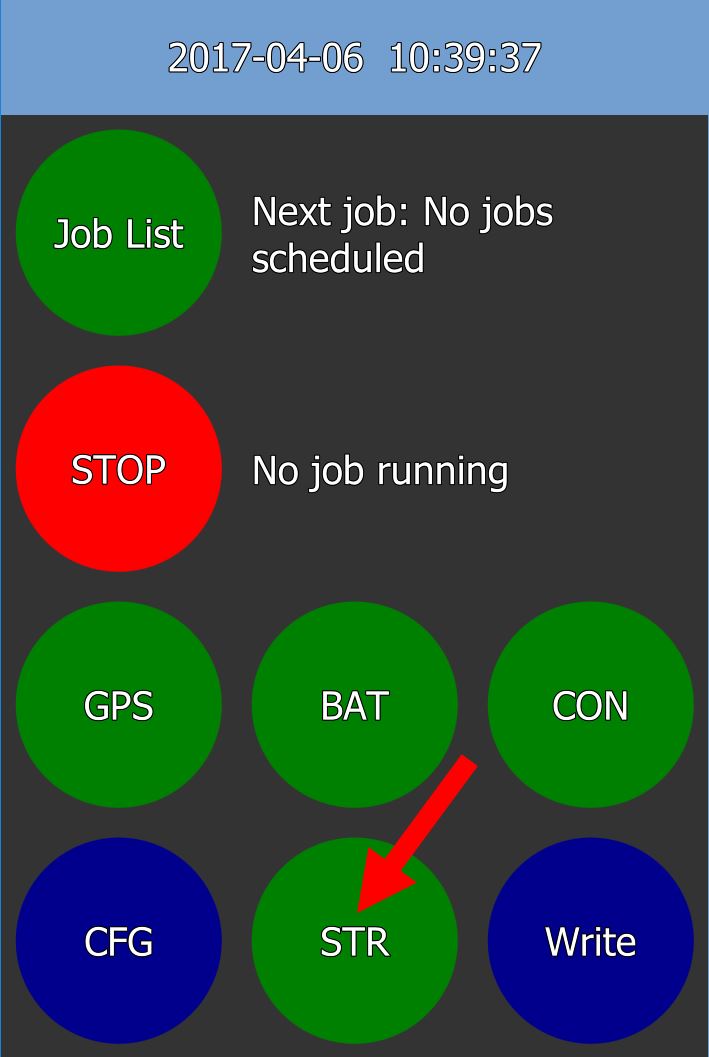
|
2.) Check the entries “Severity” and “Message” to find detailed |
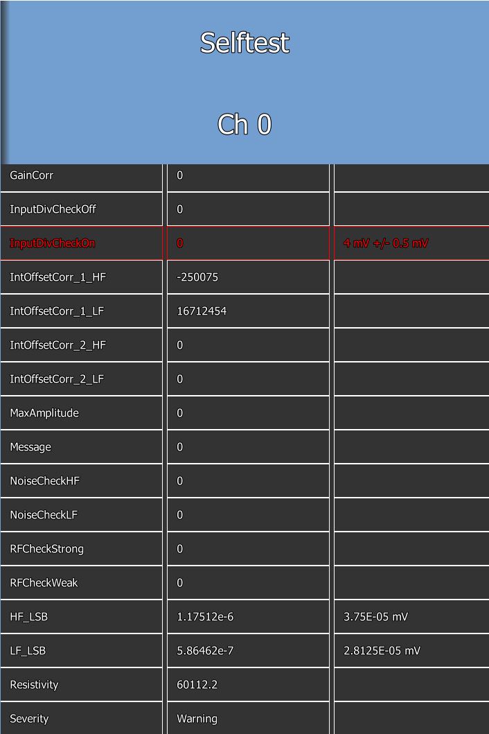
|
Web-interface:
1.) Check status on “Self-test Results” page If it is OK, the checked |

|
2.) Check the detailed descriptions of the Self-test Results error for each board. |
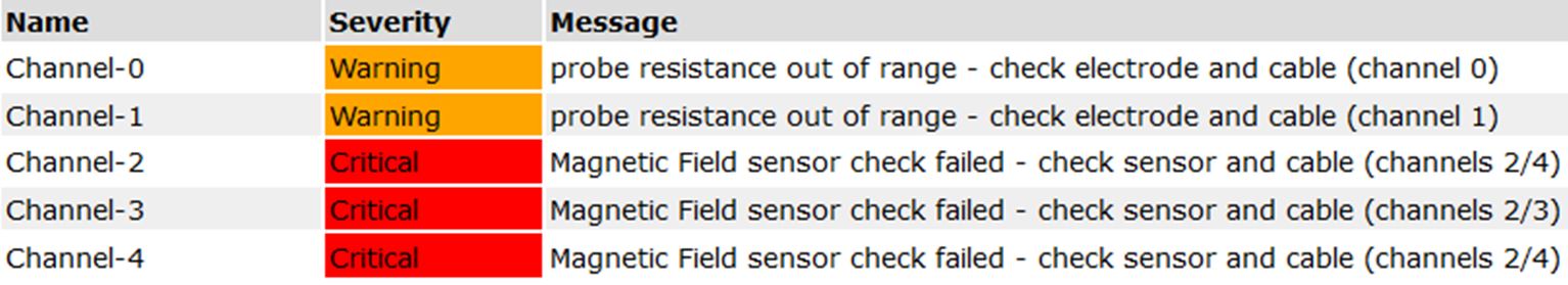
|
Note
If the Self-test Result is “Warning” the detailed self-test results should be checked. In most cases the measurement can be started.
Caution
If the Self-test Result is “Critical” the reason for the errors MUST be checked and the reason of the problem needs to be fixed before starting any measurements. Otherwise, the system behaviour may be undefined and lead to unusable measurement results.
Start Measurement
If all checks are OK, the measurement can be started, either via the Mobile App ADUCLIENT (see chapter 6), the Web-interface (see chapter 7) or by a pre-configured USB Mass Storage Device (see Job-listEditor” manual).
During the self-test the required gain- and filter-settings are determined. You should follow these recommendations and use the settings for the recording job. The App ADUCLIENT will always use the determined gain and filter settings. When using the web-interface or the job-list editor you must activate this option (Use Auto-gain/Auto-offset) as described in the corresponding chapters 7.3.1.1 or 7.3.2.7.
Front Panel Display
You can interact with the ADU-08e using the display and the buttons located on the front panel. The display provides 64 characters per line. For navigation you have these keys:

|
Function keys F1, F2, F3, F4 |
The meaning of the keys changes with the context. It is displayed in the last line of the display. |
|
Curser keys |
|
The curser keys left, right, up, down allow to navigate within the display. |
|

|
Home key |
Navigates to the Home screen. |
|

|
Back key |
Skips one menu level back. |
|

|
Enter key |
Confirms/Selects a menu entry or user input. |
|

|
Power Button |
The Power Button is used to switch on the Front-panel Display, |
Home Screen
You have 8 menu items which can be selected by the curser keys. With the ENTER key you jump into the next menu level. The maximum menu depth is three.
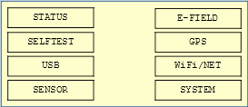
Status Menu
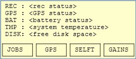
REC |
Shows the current recording status which can either be: |
Idle: no recording active of scheduled |
|
Waiting: A job is scheduled in the future and ADU-08e waits for its start-time |
|
Recording: A job is currently active and the ADU-08e is recording data |
|
GPS |
Shows the current GPS status (No fix, G1 fix, G2 fix, G3fix, G4fix). The system is only fully synchronized with G4fix status. |
BAT |
Shows the current battery status (Supply Voltage and Current drawn from the battery inputs). |
TMP |
Shows the current internal system temperature in °C |
DISK |
Shows the amount of free disk space on the data SD card |
There ar four soft keys that execute the following functions:
JOBS |
Enters the “Job Control” submenu that shows detailed information the current job status as well as the ability to stop all / the currently active job. |
GPS |
Enters the “GPS” module showing the detailed GPS status as well as providing the ability to reset the GPS (force re-synchronization). |
SELFT |
Enters the “Self-test” submenu that gives detailed information about the Self-test results of the system (including all ADB boards). |
GAINS |
Enters the “Gains” submenu showing details about the determined AutoGain values. |
Self-test
The “Self-test” menu shows detailed information about the Self-test results.
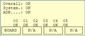
On top of the menu the status of the complete system is shown as follows:
Overall |
Status of the complete system (sum of system boards and ADB boards) |
System |
Status of system boards, like Main Backplane, Connector Board and GPS Board. |
ADB |
Status summary of the ADB boards. |
Each one of the Status may be either
OK |
All is OK – no problem with the component |
Warning |
There is an issue with the board or component – check detailed problem description |
Critical |
There is an major problem with the component – detailed problem description MUST be checked and the problem must be solved before continuing the survey. |
The softkey BOARD displays detailed results of the self-test for each board showing the status of the ADB boards Self-test result (OK, Warning, Critical), the error number index and finally the detailed error description.
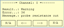
USB
This screen allows you to do operations with the USB devices connected to the ADU.
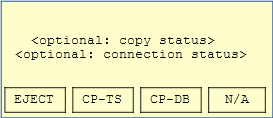
There are 3 soft keys that execute the following actions:
EJECT |
Eject a connected USB mass storage device from the system, making sure that all data is synced (safe remove). |
CP-TS |
Copy all the time series data from data SD card to the connected external USB mass storage device. |
CP-DB |
Enters the “Self-test” submenu that gives detailed information about the Self-test results of the system (including all ADB boards). |
E-Field
The “E-Field” menu shows detailed information about “Probe Resistance” (contact resistance of the E-Field probes to the ground) and the DC-Offset that was measured on the sensor inputs during Self-test.
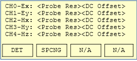
There are 3 soft keys that execute the following actions:
DET |
This will restart the Selfetst Steps that detect the sensors DC offset and probe resistance along with determining best fitting AutoGain values. |
SPCNG |
This button will lead into the “Sensor Spacing” submenu that is used to configure the E-Field spacing (see following chapter). |
E-Field Spacing
The E-Field Spacing submenu shows the currently configured spacing for the electric fields.
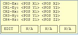
Pressing the “EDIT” button will switch to the edit mode where the spacing can be changed. All changes will become active in Webinterface and Mobile App, too.
GPS
The “GPS” submenu shows detailed information of the GPS, like position, synchronization status to GPS time and current date / time.
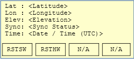
There are 2 soft keys that execute the following actions:
RSTSW |
This will do a warm-start of the GPS module, just re-synchronising to GPS |
RSTHW |
This will do a cold-start of the GPS module, resetting all known Sattelite and Almanach information |
Note
In both cases any running measurements are stopped before the GPS reset is done!
WIFI/NET
This submenu gives detailed information about the network connection of the system. It shows IP addresses currently used for LAN and WiFi.
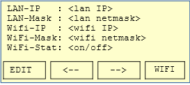
There are 2 soft keys that execute the following actions:
EDIT |
This will enter the “Edit” mode to change the IP address settings for LAN and WiFi. Once the updated network settings are saved, they will immediately become active. |
WIFI |
This will switch on/off the WiFi. Note that this will only work if an USB WiFi device is connected to the ADU-08e system. |
System
This submenu shows the last 10 messages of the ADU-08e System History (log of all executed actions).
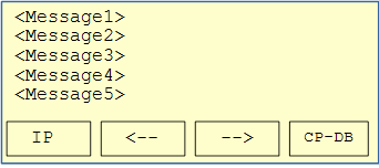
There are 4 soft keys that execute the following actions:
IP |
This will enter the “WiFi/NET” menu. |
← |
This will scroll to the next System History message. |
→ |
This will scroll to the prior System History message. |
CP-DB |
This will dump the current contents of the ADU-08e system database to disk. It can afterwards be downloaded from “<IP Address of ADU>logDBDump”. The dumped database can be send to Metronix for detailed help in case of system problems. |
Reading data from ADU-08e
The ADU-08e provides a network file system to easily read recorded measurement data from the system. For this purpose the laptop or mobile device must be connected to the ADU-08e system as described in chapter 4.2.8.1.
Additionally, the measurement data can directly be read from the ADU-08e data SD card that is accessible from the front panel.
Caution
Make sure that the ADU-08e system is powered down before you remove / exchange the data SD card.
Caution
Do not forget to insert an SD card before the ADU is started and a recording shall be made. Otherwise disk space will be very limited as the recorded data would be stored on the internal µSD card.
Reading data from Windows systems
If using a Windows™ operating system follow the following steps to connect to the ADU-08e data directory:
1.) Open “Explorer”, right click on “This Computer” and afterwards click on “Map Network Drive” |
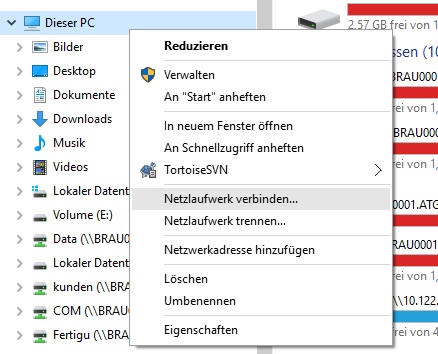
|
2.) Enter the target IP address and network drive name, e.g. \ \192.168.40.1\data And click on “Finish” |
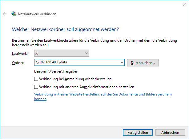
|
3.) Enter Username and Password Username: aduuser Password: neptun |
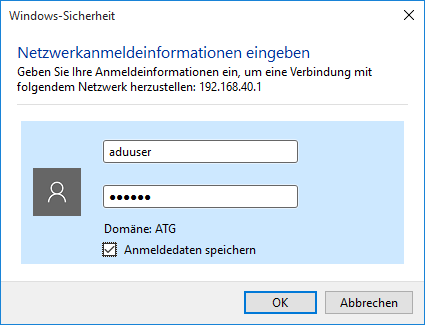
|
Now the ADU-08e data directory is directly accessible like a standard Windows network drive in your Explorer.
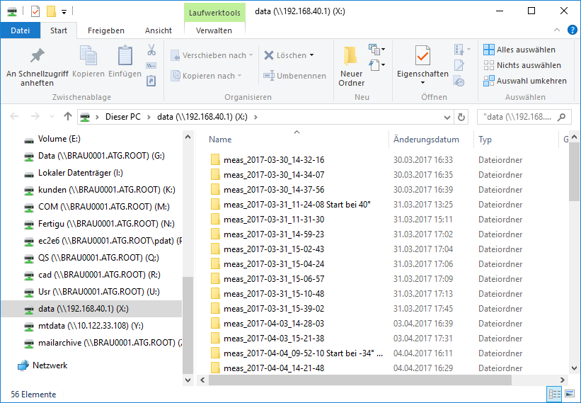
Hint
Make sure you disconnect the network drive if you disconnect from the ADU-08e system as otherwise the Windows Explorer may show very long time lags as it tries to connect to the non-existing network drive.
Hint
The time series data can be read at any time, even during an active recording.
Caution
Do not move / delete / rename directories or files that are part of the currently active measurement as this will stop the measurement as the ADU-08e is not able to write any data to those files anymore.
Reading data from Linux systems
The easiest way to read data from ADU-08e systems using a Linux Operating System is to mount the ADU-08e data network drive, using the “mount” command:
mount –o username=aduuser,password=neptun //<IP address>/data /<target dir>
As an alternative you may use the standard Linux Explorer (like Dolphin or Konqueror) and directly enter the Samba share name:
smb://aduuser@<IP address>/data
Transfer Functions
Transfer Function of HF-Channel
The theoretical transfer function for the HF-channel is given below:
\(\\F_{HF - Channel} = G_{1} \cdot F_{1} \cdot F_{2} \cdot F_{3} \cdot F_{4}\)
with
\(\\G_{1} = 1\) or 4, 8, 16 depending on gain setting of first stage
\(\\F_{1} = \frac{1}{1 + P_{1}}\) ; \(\\P_{1} = i \cdot \frac{f}{338 kHz}\)
\(\\F_{2} = \frac{1}{1 + P_{2}}\) ; \(\\P_{2} = i \cdot \frac{f \cdot G_{1} }{100 MHz}\)
\(\\F_{3} = \frac{1}{1 + P_{3}}\) ; \(\\P_{3} = i \cdot \frac{f}{1.59 MHz}\)
\(\\F_{4} = \frac{P_{4}}{1 + P_{4}}\) ; \(\\P_{4} = i\frac{f}{482 Hz}\) if high-pass is switched on.
\(\\F_{4} = 1\) if high-pass is switched off.
(gains and input divider are calibrated in the LSB, you don’t see them)
Comparison Measured Data and Theoretical Function HF
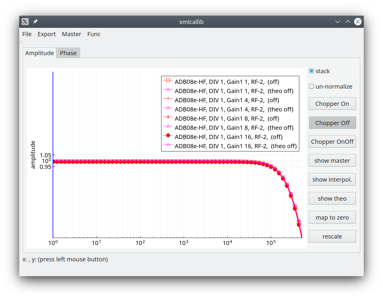
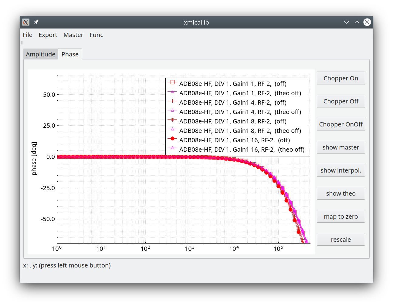
Spectra for non MT usage should be corrected above 20 kHz.
Comparison Measured Data and Theoretical Function HF with 500 Hz high pass on
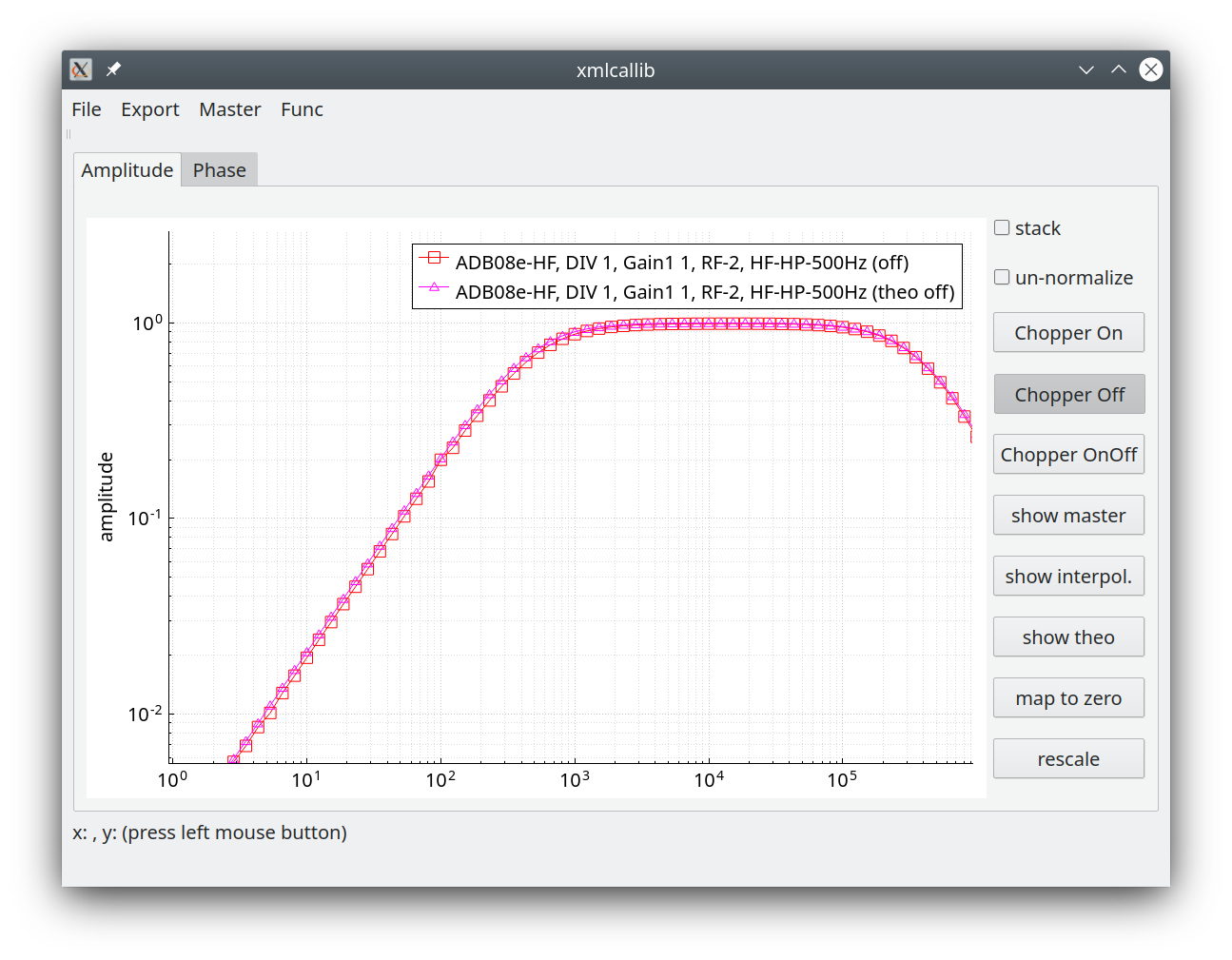
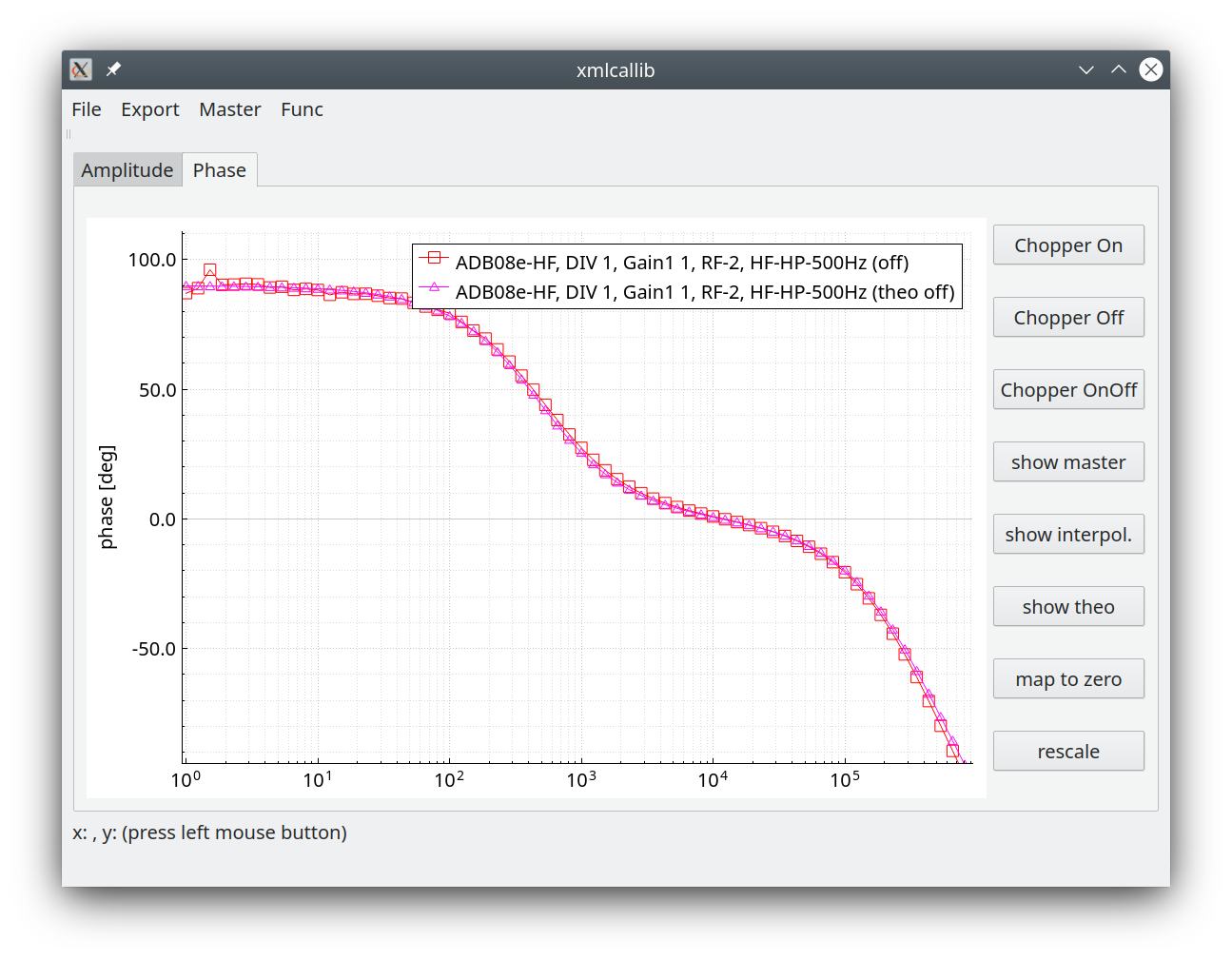
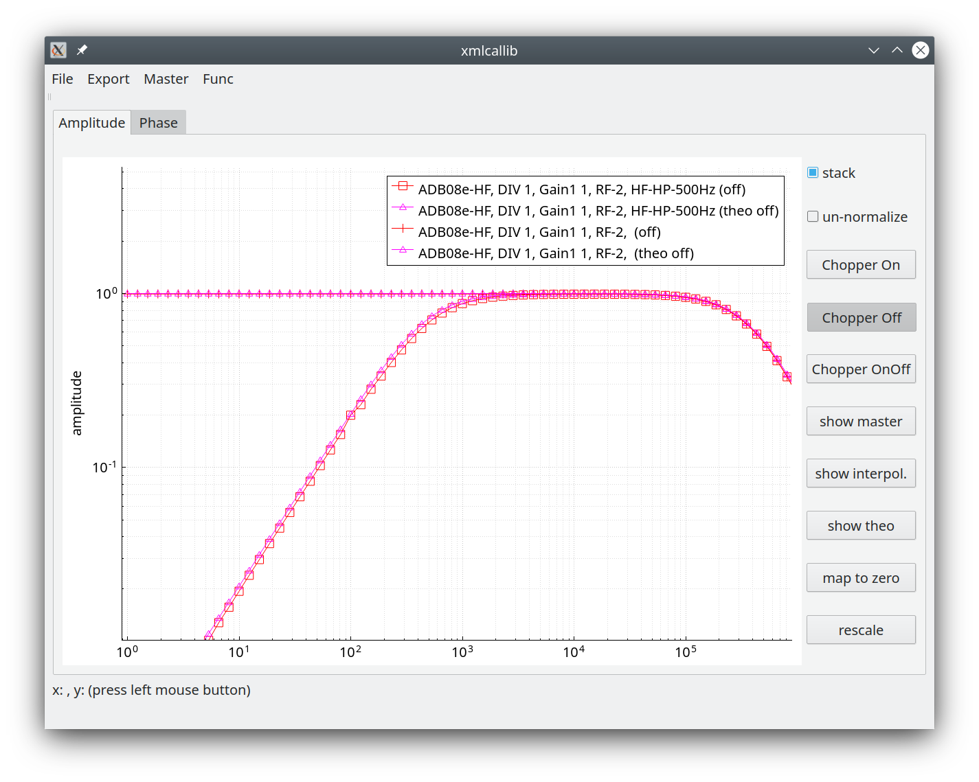
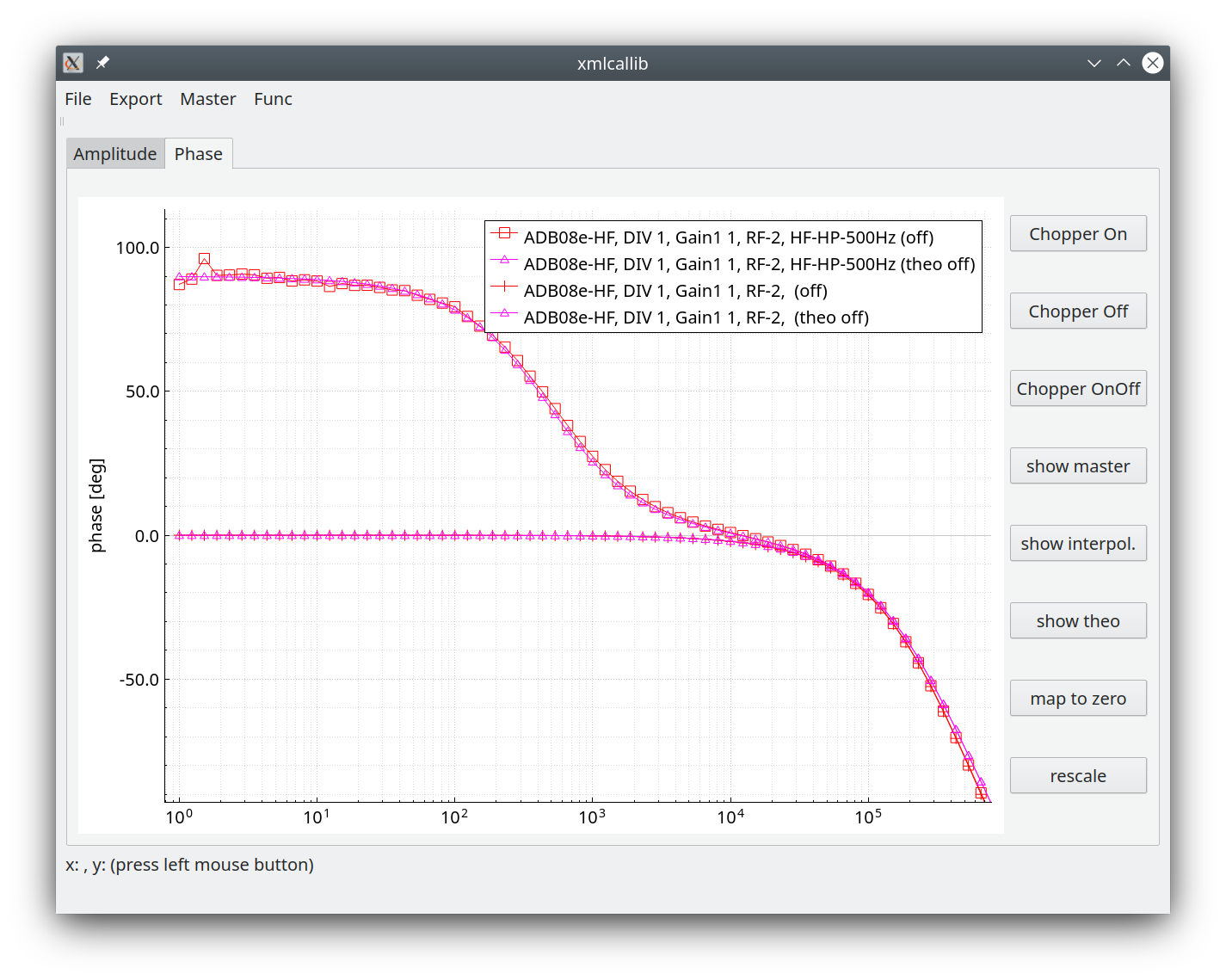
The small artefact in the measured phase is related to the fact that the signal is suppressed by the filter
Spectra for non MT usage should be always corrected
Transfer Function of LF-channel
The formula for the transfer function of an LF-channel is as follows:
\(\\F_{LF - Channel} = G_{1} \cdot G_{2} (\cdot G_{3}) \cdot F_{1} \cdot F_{2} \cdot F_{3} \cdot F_{4}\)
prefer to set \(\\G_{1}\) (gain stage 1) ONLY; 4 == excellent, 8 == perfect, 16 not needed, 1 … maybe low
Gains and input divider do not appear in the ats file, they are calibrated into the LSB
\(\\F_{1} = \frac{1}{1 + P_{1}}\) ; \(\\P_{1} = i\frac{f}{318 kHz}\)
\(\\F_{2} = \frac{1}{1 + P_{2}}\) ; \(\\P_{2} = i\frac{f }{2 MHz}\)
\(\\F_{3} = \frac{1}{1 + 1.414 \cdot P_{3} + P_{3}^{2}}\) ; \(\\P_{3} = i \cdot \frac{f}{4Hz}\) if 4 Hz Low-pass is switched on
\(\\F_{3} = 1\) if 4 Hz low-pass filter is switched off.
and
\(\\F_{4} = \frac{1}{1 + P_{4}}\) ; \(\\P_{4} = i \cdot \frac{f}{10.5 kHz}\) if RF-2 on & DIV-8 = on (default for coil, not used for E)
\(\\F_{4} = \frac{1}{1 + P_{4}}\) ; \(\\P_{4} = i \cdot \frac{f}{30 kHz}\) if RF-1 on & DIV-8 = on (not used for E)
\(\\F_{4} = \frac{1}{1 + P_{4}}\) ; \(\\P_{4} = i \cdot \frac{f}{\frac{0.159}{(R_{sensor} + 200) \cdot 7.27E^{-9}Hz}}\) if RF-2 on & DIV-1 = on (default for electrodes < 1500 Ohm contact resistance, default for buffer electrodes, not used for H) )
\(\\F_{4} = \frac{1}{1 + P_{4}}\) ; \(\\P_{4} = i \cdot \frac{f}{\frac{0.159}{(R_{sensor} + 200) \cdot 470E^{-12}Hz}}\) if RF-1 on & DIV-1 = on ( electrodes > 1500 Ohm contact resistance, not used for H)
Comparison Measured Data and Theoretical Function LF
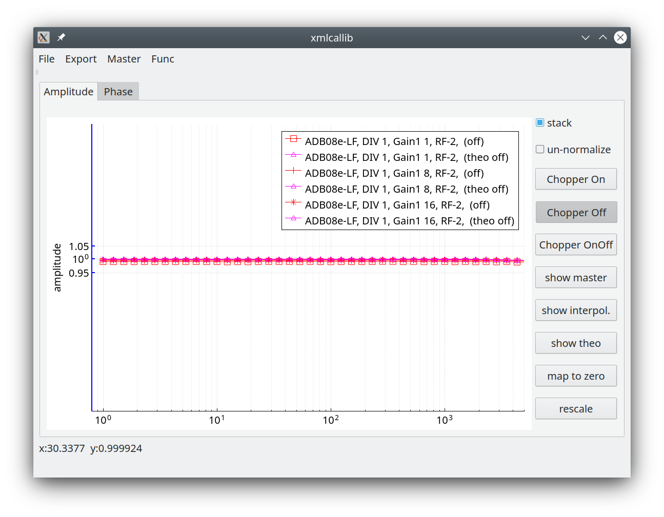
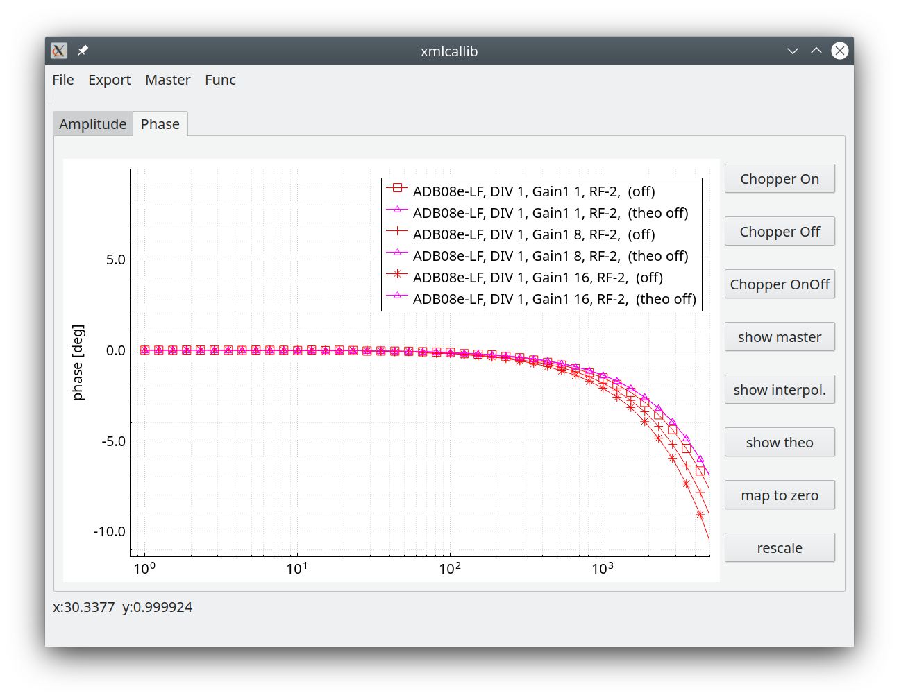
Summary
For MT corrections are useless because channels are divided.
Additionally you may use f_sample / 4 as highest interpretation frequency; with the LF Board your are also already in the linear range.
For the HF board @65 kHz you have f_sample / 4 as highest interpretation frequency 16 kHz where the influence is still tiny.
For f_sample 130, 260 and 524 kHz corrections may apply for non MT applications
Declaration of EU Conformity
The ADU-08e complies with all EU standards relevant for this product (see below).
Terms and Abbreviations
Term |
Meaning |
AC |
Alternating Current |
ADB |
Analog/Digital Board |
ADU |
Analog/Digital Unit (data logger) |
ADU-08e |
Data logger with max 6 channels E/H and sampling rates from 524 kHz downwards |
ADU-08e 2ch |
Data logger with max 2 channels E and sampling rates from 524 kHz downwards |
ADU-10e |
Data logger with 5 channels E/H and sampling rates from 256 Hz downwards |
AMT |
Audio Megnetotellurics |
ATS |
Advanced Time Series format (the data format in which the ADU stores the data – it consists of a data header and a binary data section) |
ATSS |
ATS Stream Data; palin 32bit int or 64 bit double stream |
.JSON |
corresponding header of the ATSS binary stream |
CSAMT |
Control Source Audio Magnetotellurics |
DB |
Data Base |
DC |
Direct Current |
DHCP |
Dynamic Host Configuration Protocol |
EFP |
Electric Field Probe |
FGS |
Fluxgate Sensor |
FW |
Firmware |
GNSS |
Global Navigation Satellite System |
GPS |
Global Positioning System |
HF |
High Frequency |
HW |
Hardware |
Job |
A recording job in which the start time, the stop time, the used sampling rates and the used filters are defined. |
LAN |
Local Area Network |
LED |
Light Emitting Diode |
LF |
Low Frequency |
MCP |
Master Control Program Controlsoftware on CPU Board, ADB Board, … |
MFS |
Magnetic Field Sensor |
MT |
Magnetotellurics |
RMT |
Radio Magnetotellurics |
SD |
Secore Digital Card – a storage media |
SW |
Software |
TS |
Time Series (the recorded data) |
USB |
Universal Serial Bus |
UTC |
Universal Time Coordinated |
W-LAN |
Wireless Local Area Network |
XML |
Extensible Markup Language |
Trademarks
AndroidTM is a trademark of “Google Inc”
WindowsTM is a trademark of “Microsoft Corporation”
LinuxTM is a trademark of “The Linux Foundation”
Safety Notes
The ADU is a data logger for geophysical applications. It digitizes and records data from electric and magnetic field sensors. It may only be used for this purpose. Any usage apart from this application is not covered by this manual and must be avoided.
Used Symbols
Note
Important information and notes.
Caution
Non-observance may result in severe property damages.
Danger
Non-observance may result in property damages and in personal injuries.

|
Electric Shock! Risk of electric shock. |

|
Grounding Symbol: System needs to be grounded. |
Danger Resulting From Misuse
Danger
If the ADU is used during thunderstorms it can happen that a direct lightning strike hits a connection cable especially an electric field cable. This can destroy the system.
If the ADU is operated during such conditions personal injury and even death of the operating person can occur. Operation during thunderstorms is not allowed.
Caution
The ADU corresponds to IP 6 degree of protection as well as pollution degree 5. Make sure that the environment corresponds to this degree of protection and pollution degree (IP65).
Caution
Only use replacement parts and accessories approved by the manufacturer.
Note
The safety rules and regulations of the country in which the device will be operated must be complied with.
Caution
The environment conditions defined in the product documentation must be kept. Safety-critical applications are not allowed, unless specifically approved by the manufacturer.
Note
For notes on installation corresponding to EMC, please refer to chapter 9. The compliance with the limits required by national regulations is the responsibility of the manufacturer of the machine or system.
Caution
The technical data and the connection and installation conditions for the ADU are to be found in this product manual and must be met.
Danger
The general setup and safety regulations for work on power installations (for example DIN, VDE, EN, IEC or other national and international regulations) must be complied with.
Non-compliance may result in death, personal injury or serious property damages.
Note
Without claiming completeness, the following regulations and others apply:
VDE 0100 |
Erection of power installations with nominal voltages up to 1000 V |
EN 60204-1 |
Safety of machinery - Electrical equipment of machines Part 1: General requirements |
EN55011:2009 + A1:2010 |
Industrial, scientific and medical (ISM) radio-frequency equipment – Electromagnetic disturbance characteristics – Limits and methods of measurement. |
EN61000-4-6-2014 |
Electromagnetic compatibility (EMC) - Part 4-6: Testing and measurement techniques - Immunity to conducted disturbances, induced by radio-frequency fields (IEC 61000-4-6:2013); German version EN 61000-4-6:2014 |
EN61000-4-8-2010 |
Electromagnetic compatibility (EMC) - Part 4-8: Testing and measurement techniques - Power frequency magnetic field immunity test (IEC 61000-4-8:2009); German version EN 61000-4-8:2010 |
EN ISO 12100 |
Safety of machinery - General principles for design - Risk assessment and risk reduction |
Safety Notes for Assembly and Maintenance
The appropriate DIN, VDE, EN and IEC regulations as well as all national and local safety regulations and rules for the prevention of accidents apply for the assembly and maintenance of the system. The plant engineer or the operator is responsible for compliance with these regulations:
Caution
The ADU must only be operated, maintained and/or repaired by personnel trained and qualified for working on or with the system.
Caution
Prevention of accidents, injuries and/or damages:
Take care of heavy components, like MFS-06e/07e sensors. Getting hit by these components may cause serious injuries.
Keep the electrical equipment voltage-free disconnecting the battery and protect it from being switched on, in the case of:
Maintenance and repair work
Cleaning
long machine shutdowns
-
Prior to carrying out maintenance work make sure that
the power supply has been turned off and locked, batteries have been disconnected.
The external supply battery may push very big currents, if being shorted.
Be careful during the assembly. During the assembly and also later during operation of the ADU, make sure to prevent from being flooded by water (e.g. during very heavy rain fall). Additionally take care that the maximum ambient temperature of 50°C is not exceeded, e.g. by protecting the ADU against direct impact from the sun.
Electronic devices are never fail-safe. It is the user’s responsibility, in the case an electrical device fails, to make sure the system is transferred into a secure state.
Protection against Contact With Electrical Parts
The appropriate DIN, VDE, EN and IEC regulations as well as all national and local safety regulations and rules for the prevention of accidents apply for the assembly and maintenance of the system. The survey manager is responsible for compliance with these regulations:
|
|
DANGER! Risk of electric shock! The external supply battery may push very big currents, if being shorted. |
Protection against Electrical Shock By Means Of Protective Extra-low Voltage (PELV)
All connections and terminals of the ADU are at a level of +/- 12VDC and therefore are protective extra-low voltage.
It is designed safe from contact in correspondence with the following standards:
International: IEC 60364-4-41
European countries within the EU: EN 61800-5-1
Danger
High electrical voltages due to wrong connections must be avoided!
Danger to life, risk of injury due to electrical shock!
Only devices, electrical components and wires with a protective extra low voltage (PELV) may be connected to connectors and terminals with voltages between 0 to 50 Volts.
Protection against Dangerous Movements
Not applicable as the ADU does not contains any moving parts.
Protection against Contact with Hot/cold Parts
Danger
In case the ADU is operated during very hot/cold weather the housing parts of the ADU may get very hot/cold. In this case the risk of injury is given, if the system is touched.
Protection during Handling and Assembly
Handling and assembly of certain parts and components in an unsuitable manner may under adverse conditions cause injuries.
Danger
Risk of injury due to improper handling!
Personal injury due to pinching, shearing, cutting, crushing!
The following general safety notes apply:
Note
Comply with the general setup and safety regulations on handling and assembly.
Use suitable assembly and transportation devices.
Prevent incarcerations and contusions by means of suitable protective measures.
Use suitable tools only. If specified, use special tools.
Use lifting devices and tools appropriately.
If necessary, use suitable protective equipment (for example goggles, protective footwear, protective gloves).
Do not stand underneath hanging loads.
Remove leaking liquids on the floor immediately to prevent slipping.
General Notes
In case of damage resulting from non-compliance with the safety notes in this manual, metronix Messgeraete und Elektronik GmbH will not assume any liability.
Note
Prior to the initial use you must read chapter 1.
If the documentation in the language at hand is not understood accurately, please contact and inform your supplier. Sound and safe operation of the instrument requires proper and professional transportation, storage, mechanical installation, and project planning – with a consideration of the risks as well as the protective and emergency measures – plus the proper and professional electrical installation, operation, and maintenance of the devices. Only trained and qualified personnel is authorized to handle electrical devices and systems:
TRAINED AND QUALIFIED PERSONNEL
in the sense of this product manual or the safety notes on the product itself are persons who are sufficiently familiar with the project, the setup, assembly, commissioning and operation of the product as well as all warnings and precautions as per the instructions in this manual and who are sufficiently qualified in their field of expertise:
Education and instruction concerning the standards and accident prevention regulations for the application, or authorisation to switch devices/systems on and off and to ground them as per the standards of safety engineering and to efficiently label them as per the job demands.
Education and instruction as per the standards of safety engineering regarding the maintenance and use of adequate safety equipment.
First aid training.
The following notes must be read prior to the initial operation of the system to prevent personal injuries and/or property damages:
Note
The following notes must be read prior to the initial operation of the system to prevent personal injuries and/or property damages:
These safety notes must be complied with at all times.
Do not try to install or commission the ADU before carefully reading all safety notes contained in this document. These safety instructions and all other user notes must be read prior to any work with the ADU.
In case you do not have any user notes for the ADU, please contact your sales representative. Immediately demand these documents to be sent to the person responsible for the safe operation of the ADU.
If you sell, rent and/or otherwise make this device available to others, these safety notes must also be included.
The user must not open the ADU for safety and warranty reasons.
Professional site layout and survey planning is a perquisite for sound operation of the ADU!
Danger
Inappropriate handling of the ADU and non-compliance with the warnings as well as inappropriate intervention in the safety features may result in property damage, personal injuries and electric shock.
Notes for Using ADU-07e
The ADU-07e has not many differences in operation compared to the ADU-08e.
But some things have to be set manually in the ADU-07e, that are done automatically in the ADU-08e.
A small video is here:
Environmental
In case the item is no longer needed, please dispose it according to the local regulations for electronic waste.
Dispose items only at qualified places, not in your household waste.

WEEE Reg. DE 25690185