ADU-10e
The new ADU-10e
ADU-10e
Introduction
The ADU-10e (Analog Digital Unit) is a LF logger with max. 4096 Hz sampling rate for MT and remote reference stations as well as for long term fluxgate recording.
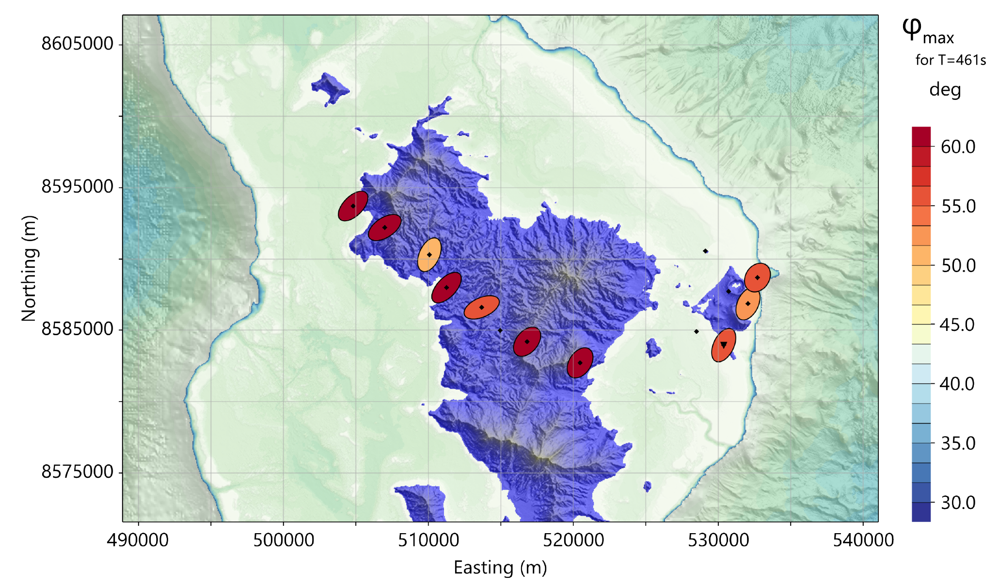
Magnetotelluric evidence for a melt-rich magmatic reservoir beneath Mayotte
Read the publication in Nature 2025:
Wawrzyniak, P., Gaillard, F., Hautot, S. et al. Magnetotelluric evidence for a melt-rich magmatic reservoir beneath Mayotte DOI 10.1038/s41586-025-09625-4. Nature 646, 1122–1128 (2025).
Data collected with metronix systems & sensors.
This is a typical survey the ADU-10e is made for: long term MT observations (in this case with remote data transmission).
Performance Characteristics
The ADU-10e has 5 channels built in and records either with 4096, 2048, 1024, 512, 256 or 16, 8 Hz using a digital filter.
Multiple ADU-10e units can be connected to a network.
Each ADU can be operated as a stand-alone system, in a network using standard Local Area Network (LAN) using Ethernet, or as part of an array, in which each unit is synchronized by its built-in GPS controlled precision clock. Access via WiFi is also built in.
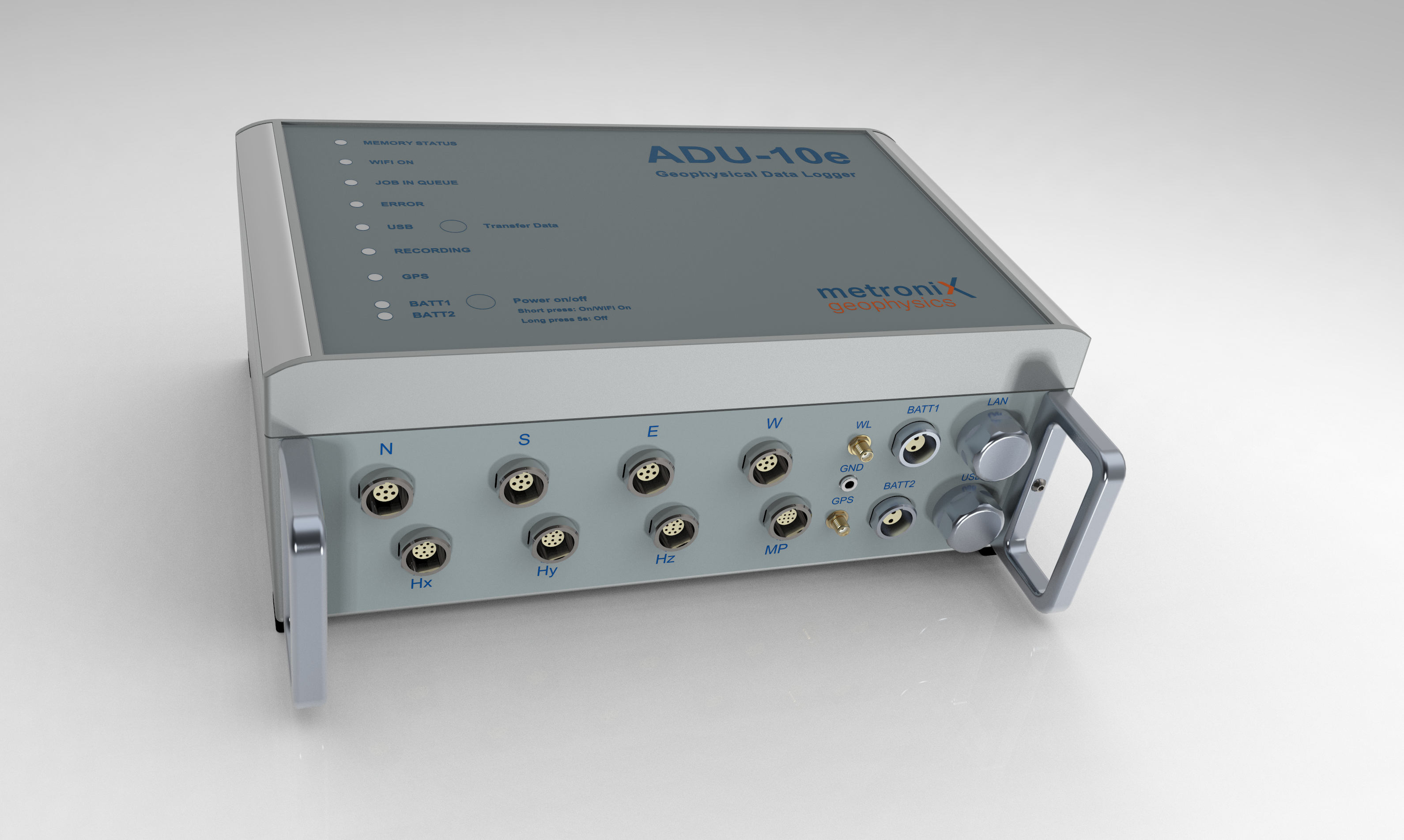
The ADU-10e electronics is housed in a small (WxHxD 33 cm x 12cm x 25 cm) waterproof box. In spite of the small size, it contains the complete circuitry for analog signal conditioning of 5 channels, 32 Bit A/D conversion and data storage as well as a very precise GPS controlled time base (using GPS, Galileo and GLONASS).
Data is stored on a removable SD card or on an USB pen drive or an external USB hard-disk or, via the network, on the hard-disk of the connected control computer.
Either the single ADU-10e or a complete network of several ADUs can be controlled via a standard PC. This may be any (ruggedized) laptop with sufficient performance.
Each ADU can be accessed and controlled by any external PC using a standard Web-browser.
All metronix magnetometers like MFS-06e, MFS-07e, FGS-03e, FGS-04e, MFS-10e and SHFT-02e & SHFT-03e can be connected directly to the ADU-10e.
The ADU-10e system provides a high degree of flexibility for various sensor setups. Due to its scalable and modular concept it can grow with the requirements of the user. The low number of different components also simplifies the spare part requirement.
Features
High data quality due to 32 Bit (LF) Analog/Digital conversion technology
Very low system self-noise
Sampling rates 8, 16 Hz and 256, 512, 1024, 2048, 4096 Hz
System can be operated as a stand-alone or as a multi-channel network system when connecting multiple ADU-10e in a Local Area Network (LAN). An integrated W-LAN module is now standard.
ADU-10e is controlled by any Web-browser without need of further software
ADU-10e is controlled by mobile phone or tablet or laptop (responsive Web-GUI)
Multiple stand-alone systems are synchronized with GPS clock accuracy.
Compatible with all metronix sensors.
Automatic unattended recording mode, pre-configured job-lists
Plug and Play recording mode if a USB stick with pre-programmed time schedule is inserted
Automatic detection of magnetometer type and automatic download of calibration function from sensor (Only for MFS-06e, MFS-07e, MFS-10e, SHFT-02e, FGS-03e/FGS-04e and future sensors)
Automated system self-check of ADU-10e and sensors during set up.
Real-time data processing on option (the capabilities of this feature will be further enhanced in future software releases).
12 V battery powered. Only one battery is required for each ADU-10e incl. sensors.
Compact, light-weight, ruggedized and water-protected instrument design.
Low power consumption
Wide operating temperature range from -30°C to +60°C ambient temperature.
Multiple methods such as MT, AMT, EMAP, CSAMT
Technical Data
Tech. Data |
Specs. |
|---|---|
Frequency range |
DC to 1024 Hz |
Number of channels |
5 |
Native sample rates of A/D converter |
4096, 2048, 1024, 512; 256, 128 … 8 Hz with integrated filter |
A/D conversion |
LF: 32 Bit (data rate max. 4096 samples/sec) |
Input resistance |
>10 MΩ E, >22 kΩ H |
Nominal input voltage range (@ gain 1) |
E: +/- 2.5 V and H: +/-10 V |
System computer |
32 bit low-power embedded controller with Linux operating system |
Storage media |
32 GByte SD card[1] (4 TB on external USB disk with ext4), USB-pen-drive or other external USB mass storage device |
Test facilities |
Automatic on power up self-test of all important system functions including sensors and display of result on the instrument. Automatic creation of log-file |
Input noise |
E @gain1: 70 nV/√Hz; H @gain1: 300 nV/√Hz |
Calibration |
automatic calibration |
Network connection |
10 MBit Ethernet with RJ45 connector, WiFi module |
Synchronization |
72 channels GNSS synchronized clock, accuracy +/-30ns rms accuracy of 1pps signal, station position is also determined and stored (GPS, Galileo, Glonass, BeiDou ) |
Standard connectors for 5 channel system |
1 x Network RJ45 10 MBit ruggedized socket(s) |
3 x Magnetometer 10-pole |
|
4 x E-field input terminal 6-pole |
|
1 x Multi-Purpose for fluxgate 12 pole |
|
1 x GND terminal |
|
2 x input 12 V battery, protected against reverse polarity |
|
1 x ext. satellite antenna SMA-Type socket |
|
1 x ext. WiFi antenna SMA-Type socket |
|
1 x USB2.0 Type A |
|
Case |
ruggedized, water-resistant alloy case |
Weight |
appr. 4.8 kg |
External dimensions |
WxHxD 33 cm x 12cm x 25 cm |
Protection |
IP67 |
Power Input |
9V … 15V DC |
Power consumption |
2.5 W[2] |
Operating temperature range |
-30°C to + 60°C |
The ADU switches Hx, Hy, Hz to the default sensor inputs or to the Multi-Purpose input. The electric channels Ex and Ey are always on the E-field inputs.
Cable Plug |
Connector (plug) |
|---|---|
E-field |
S22K0C-P06MPH0-400S ODU MiniSnap Series K |
H-field |
S22K0C-P10MJG0-700S ODU MiniSnap Series K |
Multi-Purpose |
S22K0C-P12MFG0-7000S ODU MiniSnap Series K |
Battery |
S22K0C-P02MTS0-650S ODU MiniSnap Series K |
ADU Socket |
Connector (socket) |
|---|---|
E-field |
G32K0C-P06QP00-0000 |
H-field |
G32K0C-P10QJ00-0000 |
Multi-Purpose |
G32K0C-P12QF00-0000 |
Battery |
G32K0C-P02LTS0-0000 |
You can use syncthing, rsync and WebDAV to transfer data to your office.
The system is protected against over voltage; around 16.xx V it should switch off.
All components inside the system are industrial (-40°C … +85°C) grade with the CPUs on the ADB and Clock/GPS even ranging up to 125°C.
Lightning protection is up to 4400V, fuses can be exchanged. Above the system will be seriously damaged
A MFS coil typically consumes 0.5 - 0.9 W
Tips & Tricks
With the 32 bit resolution the ADC is set to 1.185000E-06 mV for E and 4.740000E-06 mV for H. There is no further need to make gain settings.
Fluxgate
For fluxgate you may use 512 Hz sampling rate and 32x decimation. Else 512 Hz. with 32x decimation you can store more than 2 years on a 32 GB SD card.
Since the fluxgate and the electric field may have a huge drift over that time, the 32 bit ADC can play out its full strength. The signal itself may have a resolution which can easily be covered by a 16 bit ADC, but the drift is much larger (1000 x).
…
Power Surge Protection
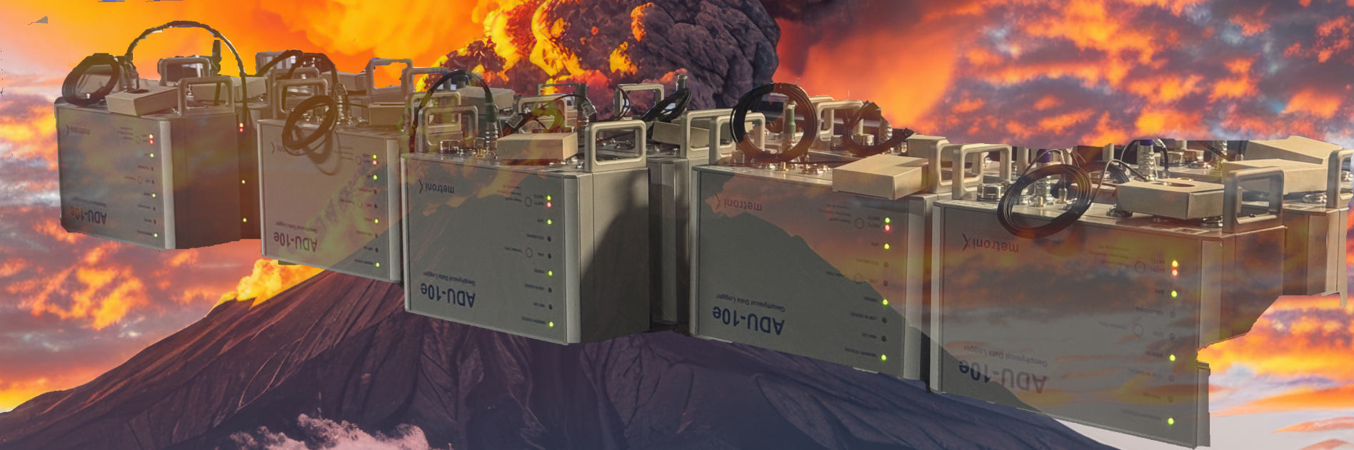
ADUs under rough conditions
In some areas with high lightning activity, the power surge protection of the system is an important aspect.
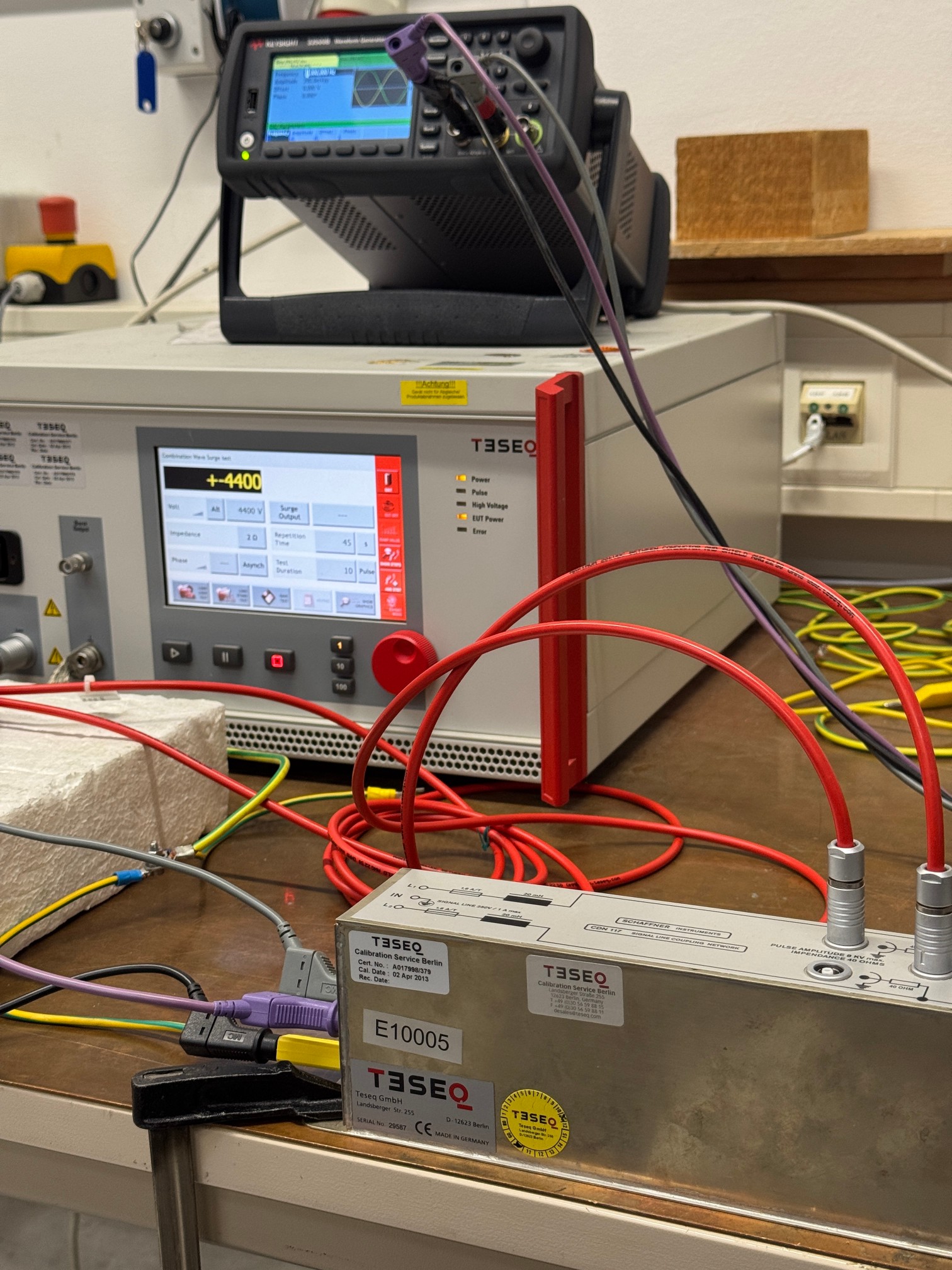
Power Surge Protection Test
The ADU-10e and ADU-11e are protected against power surges up to 4400 V and more on a 40 Ω ground (in the field you calculate 100 - 300 Ω ground, so the surge protection is even better and exceeds the 4400 V).
In case of a massive strike, the system can even repaired locally by exchanging the surge protection module.

Surge Protection Module
So the ADU-10e and ADU-11e are well suited for long term MT/AMT measurements in areas with high lightning activity like in volcanic regions.
Environmental
In case the item is no longer needed, please dispose it according to the local regulations for electronic waste.
Dispose items only at qualified places, not in your household waste.

WEEE Reg. DE 25690185