FAQ Tech
Pin Out
ADU-11e, ADU-10e, ADU-08e and ADU-07e have the same connectors since September 2011.
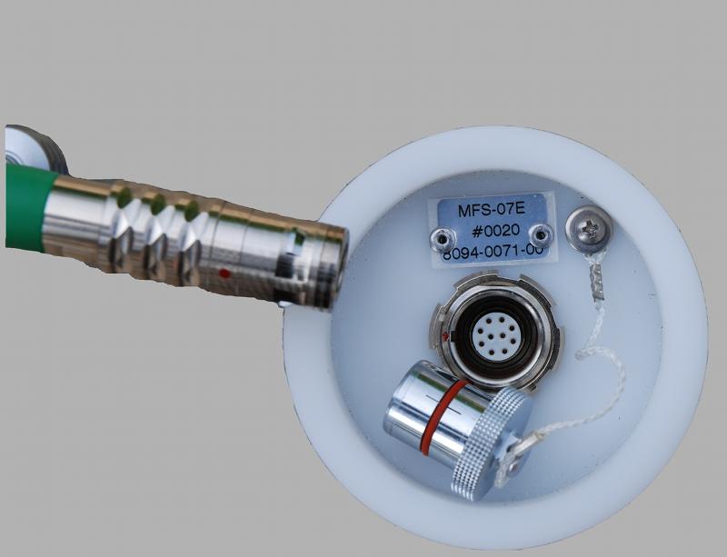
Coils MFS
MFS Side:
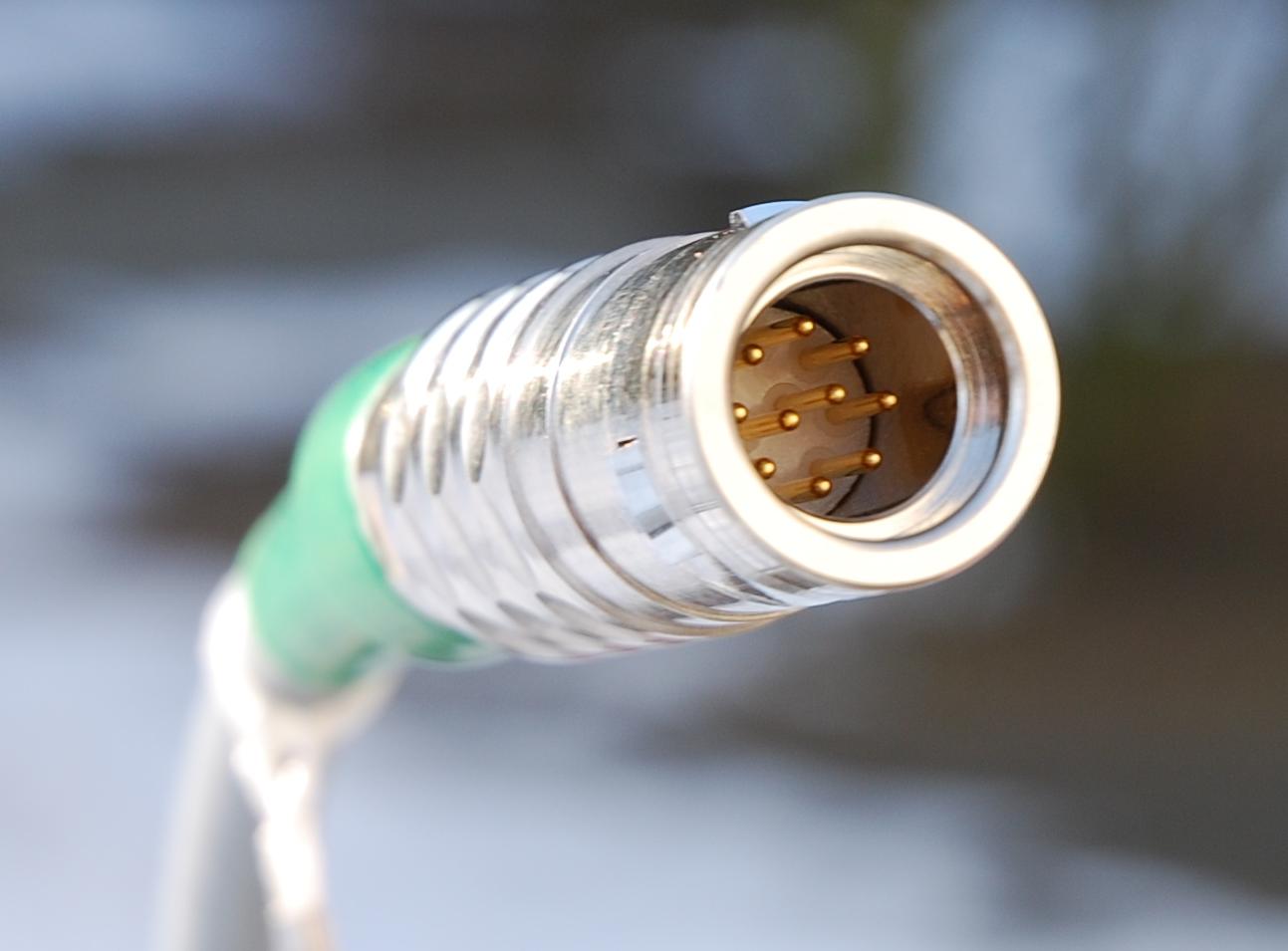
Cable Side
ODO name Convention
S22 = plug, 2 = grommet, 2 size
K = Odu MiniSnap Series K
0 = Red Dot at 0°
C = Chrome
“-”
P10 = 10 pole
“…S” solder cups
G32 = socket, 3 = rear mount, 2 size
K = Odu MiniSnap Series K
0 = Red Dot at 0°
C = Chrome
“-”
P10 = 10 pole
“…S” solder cups
so, an Sx2 needs a Gx2 socket
Pin Out Magnetic
Plug 10 pole, ODU MiniSnap S22K0C-P10MJG0-700S rear view (to solder cups) The picture below shows the front side of the socket (coil picture) or the rear side of the corresponding plug with the solder cups (so rear side of cable picture) (Socket on ADU side: ODU G32K0C-P10QJ00-0000)
Connector:
.jpg)
Socket |
Signal |
cat. |
|---|---|---|
1 |
+12V |
twisted with 9 |
2 |
-12V |
twisted with 10 |
3 (*) |
H-Chop |
twisted with 4 |
4 |
Sensor GND |
twisted with 3 |
5 |
Cal Signal+ |
twisted with 6 |
6 |
Cal Signal - |
twisted with 5 |
7 |
Input + (signal out) |
twisted with 8 |
8 |
Input - (signal return) |
twisted with 7 |
9 |
I2C SDA |
twisted with 1 |
10 |
I2C SCL |
twisted with 2 |
case |
case |
screen |
Case: screen
(*) Pin 3 is not used for MFS-12e, MFS-14e for the coil connector; cable is always fully wired.
The ODU plugs do not connect the screen. The ODU shell does not provide an electrical contact to the corresponding socket.
The MFS pre-amplifier has a resistance of ~30 Ohm and our input on the ADU side for H ~20 kOhm. The cable we use has twisted pairs (“Input +”” x “Sensor GND” ?). “Input-” is connected to GND
Pin 3 toggles the chopper. You need 5 or 12V. Pull up the gate with 12V and pull down with GND.
pull up -> pull down == chopper off
pull up -> pull down -> pull up == chopper on (there is no need to hold the 12V to keep the chopper on)
Switching does not need extra requirements since there is almost no current flow while switching.
You can order a suitable cable plug from Metronix or directly from the manufacturer ODU in Germany (www.odu.de)
The part number of the plug is ODU Minisnap Series K S22KON-T10MJG0-7000 You may also need a strain relief streeve ODU (bend protection, green) part.no. 702.023.205.965.060
Connect to another Logger
The ADU-08e has a true differential input. We connect the Sensor GND (Pin4) of the ADU with the MFS-06e sensor GND (Pin4) by the sensor cable. The negative input of the ADU (Pin8) is connected to the output - (Pin8) of the magnetometer. The positive input+ of the ADU (Pin7) is connected to the positive output+ of the magnetometer (also here pin 7).
By this means we avoid ground loops and obtain a pseudo differential behavior.
The reason why you do not see a difference in having ground connected or not when switching the chopper signal is that we provide a 100kOhms pull-down resistor on the control input against sensor GND.
Hence, when switching the supply voltage to the control input you get exactly the relay switched to the correct position. The supply voltage is referred to sensor ground.
Assuming your data logger has a differential input I recommend to provide the same cabling as described above:
Magnetometer Pin 7 to positive input of your instrument
Magnetometer Pin 8 to the negative input of your instrument
Magnetometer Pin 4 to the Sensor GND of your instrument
Magnetometer Pin 3 to a switch which provides positive supply voltage to switch chopper on
The +12V and -12V supply voltage of the sensor must be referred to sensor GND of your instrument
The cable should be twisted pair type:
Sensor output +/- must be twisted. +/-12V and chopper and sensor GND can be twisted. If you use it CAL+/- must be twisted, too. If you do not use it do not connect it at all.
Electric
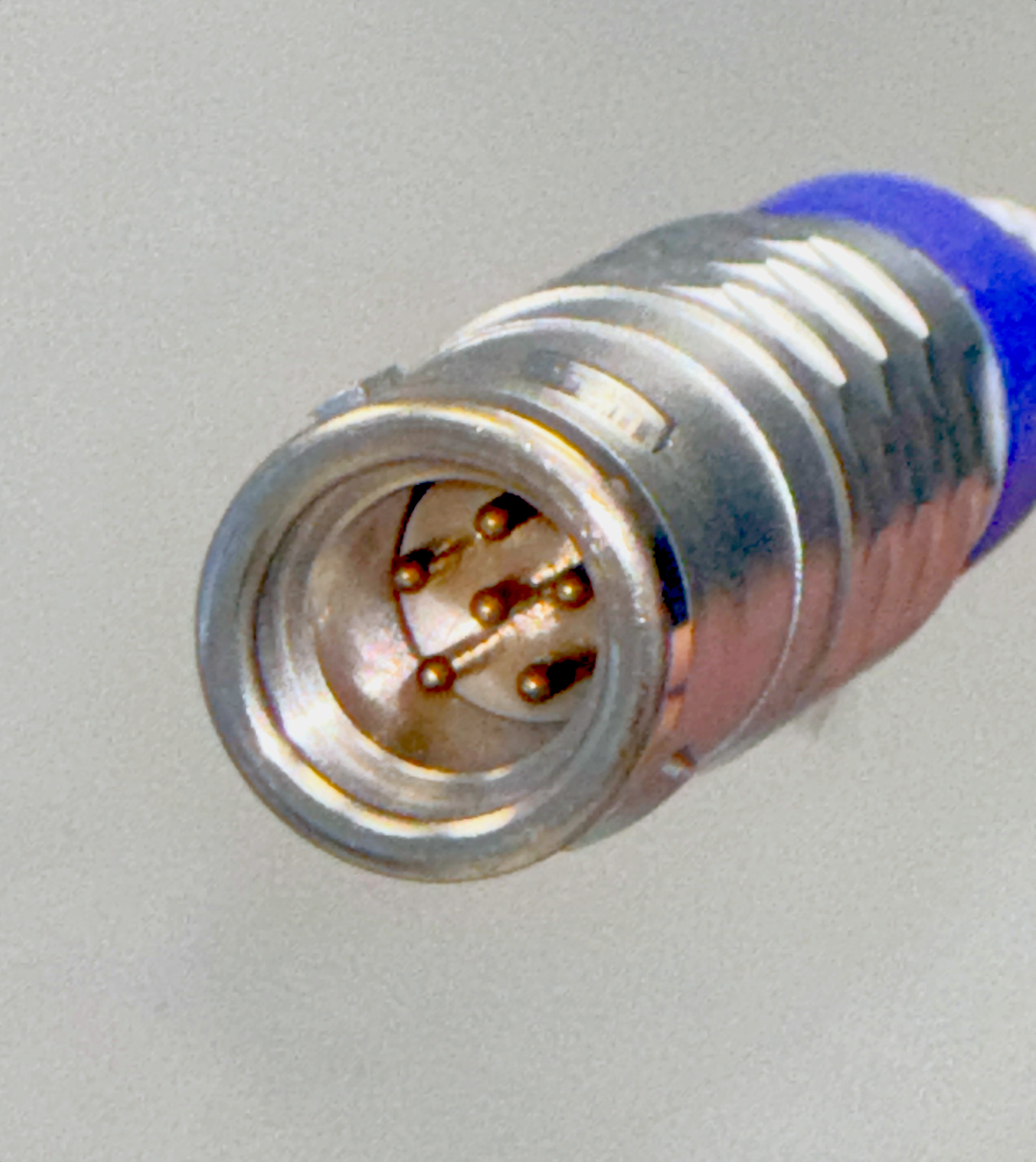
Plug 6-pole, ODU MiniSnap S22K0C-P06MPH0-400S rear view (to solder cups) (Socket on ADU side: ODU G32K0C-P06QJ00-0000)
.jpg)
Socket |
Signal |
|---|---|
1 |
+12V |
2 |
-12V |
3 |
Sensor GND |
4 |
Sensor GND |
5 |
n.c. |
6 |
Input (+ or - ) |
For standard E-field cables it is only required to connect pin no. 6
Wiring list of magnetometer cable MFS-06e/07e to ADU-07e/08e
left: Target ODU MiniSnap Series K 10 pole
right: Origin ODU MiniSnap Series K 10 pole
Battery Connector ADU-08
The connector is:
ODU S22K0C-P02MTS0-650S (plug)
ODU streeve (bend protection, blue) part.no. 702.023.206.965.040
(Socket on ADU side: ODU G32K0C-P02LTS0-0000)
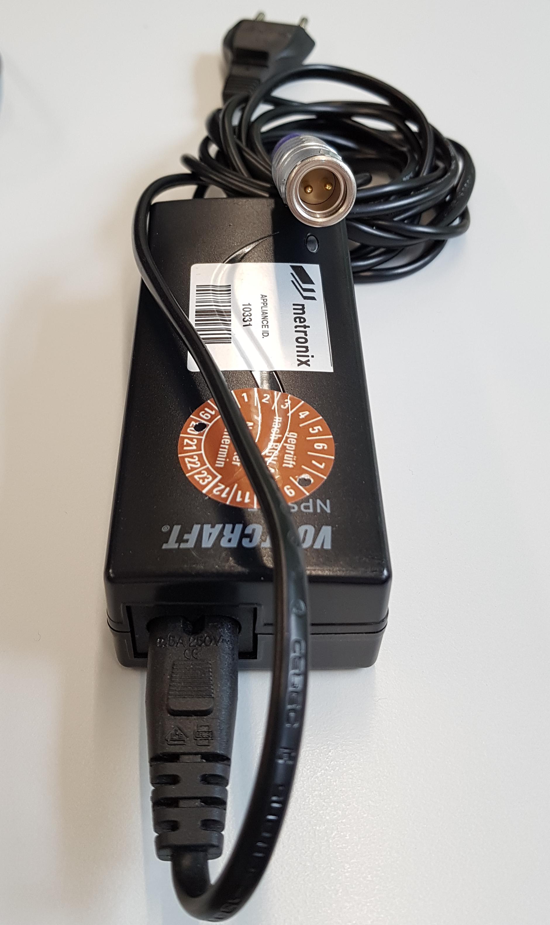
With a standard laptop charger (as shown above) 12.4A, the ADU can be operated in the laboratory easily.
Multi Purpose
Fluxgate FGS-03e, FGS-04e and newer SHFT-02e, SHFT-03e and SHFT-04e
Sensor Side |
ADU-08e 10e 11e 12e Side |
|---|---|
ODU MiniSnap Series K |
ODU MiniSnap Series K |
Plug Cable S22K0C-P10MJG0-700S |
Plug ADU side S22K0C-P12MFG0-7000S |
Socket Sensor G32K0C-P10QJ00-0000 |
Socket ADU side G32K0C-P12QJ00-0000 |
Sensor |
ADU |
Signal |
Colour |
cat. |
|---|---|---|---|---|
1 |
1 |
+12V |
white |
twisted with 9 |
2 |
2 |
-12V |
black |
twisted with 10 |
3 |
3 |
Hx Signal |
green |
\ twisted |
4 |
4 |
Hx GND |
yellow |
/ |
5 |
5 |
Hy Signal |
grey |
\ twisted |
6 |
6 11 12 |
Hy GND |
pink |
/ |
7 |
7 |
Hz Signal |
blue |
\ twisted |
8 |
8 |
Hz GND |
red |
/ |
9 |
9 |
SDATA |
brown |
twisted with 1 |
10 |
10 |
SCLK |
violet |
twisted with 2 |
11 |
GND |
|||
12 |
GND |
screen is not connected.
For the SHFT sensors the cable may not exceed 10 m.
Multi Purpose Old
Pinout and signals of multi purpose cable plug of ADU-07e
Connector:
.jpg)
Plug ODU MinSnap 30 pole S23K0C-T30MFG0-7000 |
Signal |
|---|---|
1 |
+12V |
2 |
-12V |
3 |
Sensor GND |
4 |
Sensor GND |
5 |
Input A + |
6 |
Input A - |
7 |
Input B + |
8 |
Input B - |
9 |
Input C + |
10 |
Input C - |
11 |
Input D + |
12 |
Input D - |
13 |
Input E+ |
14 |
Input E - |
15 |
Cal Signal + |
16 |
Cal Signal - |
17 |
n.c. |
18 |
HCHOP CH7 |
19 |
HCHOP CH8 |
20 |
HCHOP CH9 |
21 |
I2C_SDA5 |
22 |
I2C_SCL5 |
23 |
I2C_SDA6 |
24 |
I2C_SCL6 |
25 |
I2C_SDA7 |
26 |
I2C_SCL7 |
27 |
I2C_SDA8 |
28 |
I2C_SCL8 |
29 |
I2C_SDA9 |
30 |
I2C_SCL9 |
Please download Pinout and order numbers of ADU-07e connectors.pdf
ADU-07 (old)
Please download Pinout and order numbers of ADU-07 sensor connectors.pdf
(SACC-MS-5CON-PG 7-M SCO)
GFZ SJT Connector
socket |
signal |
cat. |
|---|---|---|
1 |
+12V |
\ twisted |
2 |
-12V |
/ |
3 |
||
4 |
Sensor HCHOP |
\ twisted |
5 |
Input GND |
/ |
6 |
||
7 |
+CAL |
\ twisted |
8 |
-CAL |
/ |
9 |
||
10 |
Signal out |
\ twisted |
11 |
Signal return |
/ |
12 |
||
13 |
GFZ SJT Connector 2019 (proposal)
socket |
signal |
|---|---|
1 |
+12V, twisted with 12 |
2 |
-12V, twisted with 13 |
3 |
|
4 |
Sensor HCHOP, \ twisted |
5 |
Input GND, / |
6 |
|
7 |
+CAL, \ twisted |
8 |
-CAL, / |
9 |
|
10 |
Signal out, \ twisted |
11 |
Signal return, / |
12 |
I2C SDA, twisted with 1 |
13 |
I2C SCL, twisted with 2 |

Rear view.
Precision of Current Measurement TXM TXB
The LEM modules measure the transmitted currents with tolerance < 1% (±0.9% @T=25°C) The LEM modules are operated at ±12V DC stabilized (input resistance Rm 50 Ohm). Please download 1639877.pdf
USB WiFi Dongle
The ADU-07e and ADU-08e need a WiFi dongle in order to use the WiFi. The dongle can be connected to any USB port; the inside port or the outside port with extra cable in order to get it out of your box.
Not any dongle works. Take the LogiLink WL0086B. Amazon ASIN B00AAWKZRQ or EAN: 4052792005202 With some luck: LogiLink direct
SD Cards
Following SD cards should work:
Transcend 32 & 64 GB
Samsung 256 GB … to be tested, may has a problem!
Please also take a look here
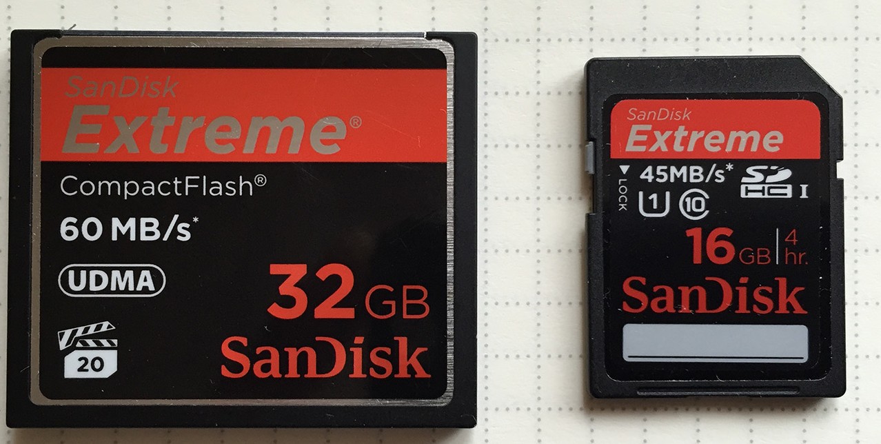
left: old compact flash card, right SD card The compact flash was used for GEODE boards until October 2013. Some users replaced the CPU board with more efficient IGep board with SD card.
GPS Antenna
We use “Planar Navigations Antenna N60XAD_WP High Gain”, model N60XAD_0300_XX_03_WP
Frequency Range 1575.42 MHz
VSWR* 1.5 typically
Peak Gain* 25 dBi typically
Power Supply 3V to 5V; 25mA typically
GPS module
HS Commodity Code 90159000
The module does not need an extra license when ordered for ADU-07e/08e spare part (as at May 2020)
Bluetooth & WiFi
Bluetooth & WiFi transmit above 2 GHz (or 5 GHz). In general the sensors don’t see that.
However when the transmission is pulsed (like the old mobile phones did) you can get significant distortions. Mostly the DC/DC converters (power stabilized 12V adapter) can cause trouble. This is mostly also the noise source of solar panels. There is nothing to do but testing.
Leutron E-Field Protection
For a better protection against over voltage from the E-Field we recommend to use the Leutron E-Field protection. The Leutron E-Field protection is a small box which is connected between the electrode and the ADU.
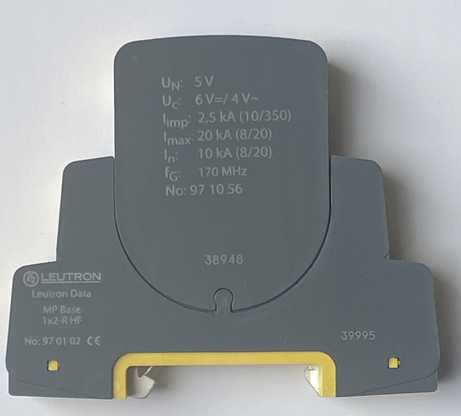
opened:
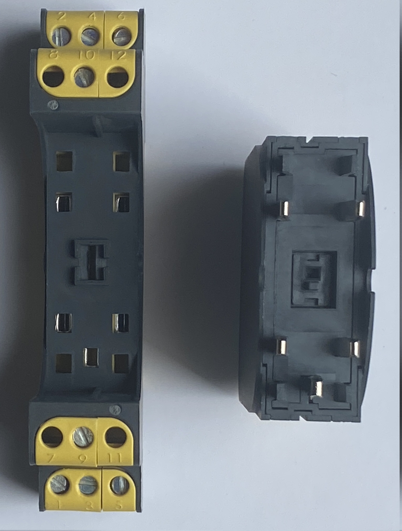
Leutron MP Base 1x2-R HF, No. 97 01 02 and Leutron MP 1x2 5 V-170-HF ST, No. 97 10 56 Contact a local dealer or Leutron directly: www.leutron.de You need two of them, N-S and E-W.
No. 97 01 02: commodity code: 85363090, Country of Origin: Germany, weight: 0.062 kg
No. 97 10 56: commodity code 85363090, Country of Origin: Germany, weight: 0.038 kg
Example - usage on a field site we put the modules in a little box:
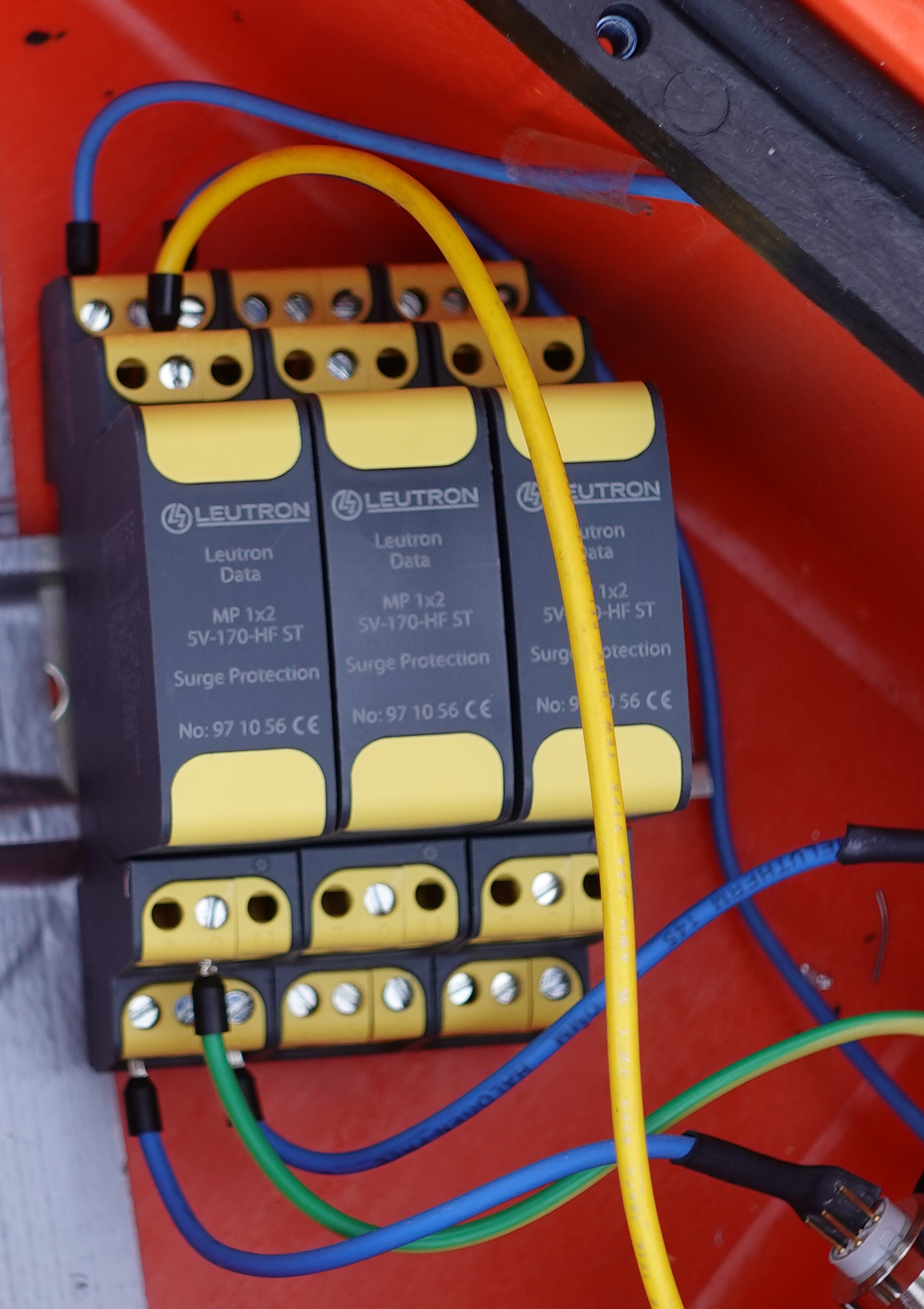
You see 2 times a blue cable: North Line and South line; The yellow and green bridges the ground. … so in this picture ONE dipole (N-S) is connected. Repeat this for the second dipole (E-W). And in rare cases for a power supply in great distance. During this comparison the second module was not used (the third will be never used but is unfortunately on the picture). For field measurements the second module will be connected to the East and West line the same way. You have to shorten the ground line between both modules.
We have tested the modules in the laboratory and in the field. There are no visible differences.