TXM-22 / TXB-08
THIS TRANSMITTER IS DISCONTINUED
Product Description
Performance Characteristics
The TXM-22 is a highly efficient multi-purpose geophysical transmitter. It is used in connection with the TXB-08 transmitter controller. Along with it a geophysical transmitter suitable for controlled source applications such as Controlled Source Audio Magnetotellurics (CSAMT), Controlled Source Electro Magnetics (CSEM) or Long Offset Transient ElectroMagnetics (LOTEM) is provided.
It can be operated in a wide frequency range between 0.001 Hz up to 8,192 Hz. The output current is adjustable up to a maximum of +/-40A. The nominal output voltage is +/-560V.
The TXM-22 is powered by a 50/60Hz, 3-phase, 400V motor generator. In order to unleash the full capabilities a generator of min. 40kVA should be used.
The output currents can be fed into 3 electrodes, thus offering the possibility to rotate the current vector in any direction. The TXB-22 uses a pulse-width modulation (PWM) to generate the output signals. By this means it is possible to create different wave forms on the output such as sine wave, square wave, triangle, saw-tooth or PRBS. For frequencies higher than 2048 Hz the TXM-22 will transmit a square wave only.
The TXB-08 is synchronized by GPS and can be programmed using a laptop which is connected by LAN or W-LAN. It also can be controlled by a USB stick which contains a pre-programmed job-list. Optionally, it is possible to record time series of the currents which are fed into the three electrodes.
The user friendly control software provides a comfortable access to all relevant control parameters of the TXM-22.
Features
Wide frequency range from 1/1024 Hz to 8192Hz
Rotation of current vector due to 3 electrode outputs
Pre-defined or user defined arbitrary waveforms
Execution of pre-defined joblists
Recording of Electrode current as ATS time series file (option)
W-LAN interface
24 Bit Analog/Digital conversion technology for optional current amplitude recording.
Optional control via Cell Phone and VPN (Virtual Private Network)
Synchronization with GPS clock accuracy.
Plug and Play recording mode if a USB stick with pre-programmed time schedule is inserted
Automatic system self check of TXM-22 and TXB-08 during start-up.
Operating temperature range from -10°C to +40°C ambient temperature.
Technical Data TXM-22
Frequency range |
1024 sec to 8,192 Hz |
Power Input |
motor generator 40kVA, 400V, 3-phase, 50/60Hz |
Output Current |
max. +/-40A continuously |
Output Voltage |
+/- 560V |
Load |
grounded dipoles or horizontal loop |
Transmitter signal wave forms |
Predefined (sine, square wave, triangle, saw-tooth) or user defined arbitrary wave forms such as PRBS signals with a max. number of 2,048 set-points. For frequencies higher than 512 Hz square wave is available only. |
System control |
by transmitter controller TXB-08 |
Test facilities |
Automatic power up self-test of all important system functions |
Case |
ruggedized, water protected aluminium case |
Weight |
ca. 35kg |
External dimensions |
480mm x 514mm x 354mm |
Operating temperature range |
-10°C to + 40°C |
Technical Data TXB-08
Interconnection cable to TXM-22 |
19-pole, 5m, galvanically decoupled |
System Control |
by external laptop or by pre-programmed USB-Stick |
Signal Waveforms |
predefined waveforms or freely programmable by user up to 512Hz |
Ratio for current measurement channels |
25mV/A |
Number of measurement channels |
3 |
A/D conversion of current measurement channels |
24 Bit (data rate max. 65,536 samples/sec) |
System computer |
32 bit low-power embedded controller with Linux operating system |
Storage media |
Internal Compact Flash-disk 4Gbyte or higher, USB-Stick or external USB mass storage device |
Test facilities |
Automatic power up self-test of all important system functions |
Network connection |
stand. twisted pair Cat5 or higher with RJ45 plugs Wireless-LAN -GSM Modem (option) |
Synchronization |
GPS synchronized clock , 30ns rms accuracy of 1pps signal, Station position is also determined and stored |
Status Display |
2 lines with16 alpha numeric characters for display of status information |
Case |
ruggedized, waterprotected plastic case |
Weight |
6.6kg |
External dimensions |
406*330*174mm3 |
Power Input |
9V..15V DC, usually powered by TXM-22 |
Operating temperature range |
-30°C to + 60°C |
Revision base for this manual
The functionality that is described in this manual is based on the following revisions of software and hardware components of the TXM-22 system:
Hardware components:
Name |
Description |
Revision |
ADU07-ADB-LF |
LF analog/digital converter board |
1.0 |
ADU07-ADB-HF |
HF analog/digital converter board |
1.0 |
ADU07-MDB |
ADU-07 mother board (main backplane) |
2.1 |
ADU07-FPGA |
ADU-07 FPGA and USB board (sub backplane) |
1.0 |
ADU07-CLK |
GPS/clock board |
1.0 |
ADU07-CAL |
Daughter board for creation of calibration signals |
1.0 |
TXB07-CON |
Connector board |
0.1 |
TXM-22 |
Power Stage for TXM-22 system |
1.0 |
Software components:
Name |
Description |
Revision |
MCP |
Master Control Program for TXM-22 operation |
2.4.0.1.XXX |
USB driver |
Linux USB driver for connection of the backplane to the CPU board |
2.3.0.1.107 |
TXM-22 User Interface |
User Interface for TXM-22 system |
2.4.0.1.XXX |
8051 software |
Embedded controller software for backplane |
2.4.0.1.XXX |
FPGA image |
VHDL FPGA image for backplane hardware control |
3.9 (23.04.2010) |
USB Automounter |
Auto detection of connected USB mass storage devices with pre-configured job-lists |
1.2.0.1.32 |
Overview TXB-08
The TXB-08 comes with a GPS-antenna, two battery cables and a short network cable.
Figure 5-1 to 5-3 shows the TXB-08 and its operating elements. All operating elements are numbered and described in more detail in the next chapter.
image Operating elements of TXB-08 front-panel
image Operating elements of TXB-08 left side
image Operating elements of TXB-08 right side
Operating Elements
The TXB-08 has the following operating elements:
Name |
Function |
1 |
2 x USB Type A connector |
2 |
1 x USB Type B connector |
3 |
GPS Status LED |
4 |
Recording Status LED |
5 |
Battery Status LED |
6 |
Button “SCROLL” |
7 |
Button “PARAM” |
8 |
Alpha numerical display |
9 |
Battery connector 1 |
10 |
Button “Power Stage Off” |
11 |
W-LAN antenna Option 2: GSM modem antenna |
12 |
GPS-antenna |
13 |
Battery connector 2 |
14 |
LAN 1 (RJ45) |
15 |
Link to TXM-22 |
Table 5-1: Operating Elements of TXB-08
USB Type “A” Connector
Underneath the lid you will find 2 USB connectors allowing to connect USB mass storage devices such as USB memory sticks or USB hard-drives. Mass-storage devices will be recognized by the operating system automatically.
USB Type “B” Connector
With this connector one can attach an external computer to the TXB-08. The external computer must be run with Linux operating system and the appropriate software to control the TXB-08 has to be installed. If the external computer is connected to the TXB-08 it will switch off the internal CPU board automatically. The external computer will then control the TXB-08 completely. This option is intended for debug purposes mainly.
GPS status LED
This LED shows 3 states:
LED off |
No GPS synchronization or system in clock hold mode |
LED blink |
System has detected sufficient number of satellites, but has not reached the maximum accuracy |
LED steady green |
GPS locked and system fully synchronized |
If the LED is not illuminated despite the GPS-antenna is connected properly, it may be that the antenna does not have an open view to the sky allowing the system to detect at least 4 satellites in view. In this case it may be helpful to use another antenna location.
If the TXB-08 has been moved to another location which is far away from the last one with a valid GPS lock, it can take a while until the system has found a sufficient number of satellites. In this case the stored Almanac of the satellite position is no more valid for the new location and has to be updated first. This procedure can take up to 15 minutes.
Recording status LED
This red LED is illuminated if a data acquisition of the transmitter currents takes place.
Battery Status LED
This LED provides quick information about the battery voltage. The meaning of the different colours is:
Green |
Battery good (voltage higher than 12.5V, fully charged) |
Yellow |
Battery voltage fair (<12.5V and >11.6V) |
Red |
Battery low (voltage < 11.6V and > 11.2V) |
Dark |
Battery almost totally discharged (voltage <11.2V) |
The exact battery voltage and current is also displayed on the status display and is monitored in the log file. It is also shown in the TXM-22 control software.
Alpha Numerical System Status Display
The display shows the status of the system after self test as well as many other important parameters and information. It is automatically switched off after a period of 30 sec if no button is pressed.
Battery Connector
The TXB-08 is equipped with 2 battery sockets (type CA 02COM-E10SL-4S-B). This allows to connect one or two batteries. Before the delivered battery cable can be connected, you have to unscrew the protection cap of the socket. The input voltage is 12 V nominal; the allowed voltage spans from 9V to 15V. The inputs are protected against wrong polarity under all circumstances. If the TXB-08 should not work, check for wrong polarity. Usually the TXB-08 is powered by the TXM-22 via the control cable.
Antenna Socket for W-LAN
The W-LAN antenna socket allows you to connect an external antenna in case the built-in antenna is not sufficient.
Antenna Socket for GPS Antenna
The GPS-antenna which is delivered along with the TXB-08 must be connected to this socket (N-type) to get advantage to the synchronous recording mode and in order to determine the systems position.
Socket for Network
A network cable can be connected to this socket (RJ45). The operation of the network is described in a separate chapter.
Interconnection Socket to TXM-22
The TXM-TXB cable is connected to this socket. Via this cable the communication between TXB-08 controller and the power stage TXM-22 is done. It also provides the power supply of the TXB-08 if the TXM-22 is switched on.
Operating Elements TXM-22
The TXM-22 is delivered with a cable to connect it to the TXB-08 controller. On standard this cable has a length of 5m.
The picture below shows the TXM-22 transmitter and its operating elements.
image Location of operating elements of TXM-22 front-panel
Name |
Function |
1 |
Fan (air exhaust) |
2 |
Fan (air suction) |
3 |
Power input 400V AC, 3-phase |
4 |
Push-button power on |
5 |
LED “24V Power Good” |
6 |
LED “Ready” |
7 |
LED “Error” |
8 |
LED “Output Active” |
9 |
Socket for cable TXB-TXM |
10 |
Power Off switch |
11 |
Output Electrode 1 |
12 |
Output Electrode 2 |
13 |
Output Electrode 3 |
14 |
Output of current measurement Electrode 1 |
15 |
Output of current measurement Electrode 2 |
16 |
Output of current measurement Electrode 3 |
17 |
Customer specific output (not standard) |
Air Exhaust
The warm air is blown out by 2 electric fans.
Caution
The openings may not be covered. Free airflow must be possible. Otherwise anoverheating of the instrument may occur.
Note
The filter mat may be cleaned from time to time. For this purpose the grill can be taken off. Remove the mat and wash it in water. It must be completely dry before re-insertion.
Air Suction
The outside air is sucked in by an electric fan for cooling purpose.
Caution
The openings may not be covered. Free airflow must be possible. Otherwise anoverheating of the instrument may occur.
Note
The filter mat must be cleaned from time to time. For this purpose the grill can be taken off. Remove the mat and wash it in water. It must be completely dry before re-insertion.
Note
The TXM-22 produces heat during operation. The temperature depends on the current – the higher the current the more heat is produced. Observing the power stage temperature which is displayed on the front-panel display of the TXB-08 and on the user interface will show whether the cooling is sufficient. You must avoid temperatures higher then 68°C. In this case you should switch off the output stage for a while or reduce the current.
400V Power Input
This input is used to connect the external 400V power source to the TXM-22. The mating connector is delivered along with the instrument. The type is a cable socket 32A, 400V according to IEC 60309 with 5 poles. The figure below shows the pinout of the connector:
LED “24V Power Good”
This LED is lighted if the TXM-22 is started. It indicates that the 24V internal power-supply works correctly.
LED “Ready”
This LED is lighted if the serial data interface between TXB-08 and TXM-22 is working alright.
Note
The TXM-22 and the TXB-08 must be connected by the delivered control cable before starting the TXM-22. Otherwise the initial communication between the 2 systems cannot take place and the “Ready” LED will not be lighted.
LED “Error”
The LED is not used presently.
LED “Output Active”
Indicates whether the power stage output is active. A high voltage of more than 500V is generated on the electrode output sockets if lighted up.
Socket for Cable TXM-TXB
This 19-pole socket provides the necessary control lines to interfere between TXB-08 and TXM-22 as well as the power supply of the TXB-08. Analog voltage signals of the measured phase currents are also available here. In case the TXB-08 is equipped with A/D converters it is possible to record the transmitted currents on flash card.
Power-Off Switch
Pressing this switch will immediately switch off the TXM-22. The power input and the power output will be cut. Before the system can be restarted with the On-switch it is required to pull the Off-switch again.
Electrode Output Sockets E1,E2,E3
These sockets (11,12,13) deliver the output signal of the TXM-22.
Caution
You may only use the mating plugs to connect your electrode cables with the TXM-22. Three of these plugs are delivered along with the TXM-22.
Outputs for Current Measurement
These outputs (14,15,16) provide a voltage corresponding to the measured current in the electrode cables. The ratio is 25mV per Ampère.
Customer Specific Output
This output is not available on standard TXM-22.
Installation in the Field
The following chapters describe the installation of the TXM-22 geophysical transmitter. Please carefully follow these instructions in order to guarantee a safe operation. The picture below shows a block-diagram of the arrangement.
Caution
In order to avoid electrical hazards a suitable isolation transformer must be installed between motor generator and TXM-22!
image Block diagram of the transmitter arrangement
Transmitter Location and Electrode Setup
First step is to find a suitable transmitter location. In most cases you will use grounded dipoles to inject the current. In order to get the optimum symmetric situation it is desirable to locate the transmitter in the centre of an equal sided triangle which has an electrode installed on each tip. The picture below shows this arrangement. Often, it will not be possible to get this ideal arrangement and you will be forced to have a different electrode setup. In order to get a reasonable dipole moment into the ground the cable length should be between 300m to 1000m for each of the 3 wires. The electrodes are connected to the cables. Lay out the cables up to the transmitter. Now you should measure the resistance of the electrodes. You can use a professional ground resistance meter or you use a 12 V car battery and measure the current between two electrodes with a multi-meter. Now you can calculate the resistance according to Ohm´s law Resistance (Ohm) = 12V/I where I is the current displayed on the instrument. The lower the resistance the better it is. Only if the resistance between the electrodes is less than ca. 14 Ohm it will be possible to achieve the max. current. of 40A. A higher resistance will cause the maximum current to be lower.
Different configurations of electrodes can be used: It can be one or several rods which are rammed into the soil. If several rods are used they have to be connected with each other.
Another possibility is to use metal sheets which are dug into pits possibly filled with (salt) water to improve the contact resistance. The electrodes and the cables should be setup in a way that they can be observed by the electrode watches.
image Arrangement of transmitter electrodes (ideal situation)
Motor Generator
The motoer generator must be levelled horizontally. The power cable should not be connected on the generator yet. Position the TXM-22 and the isolation transformer (ideally mounted on a second trailer) near the motor generator considering the length of the power cable.
Electrode Connection
Now, open the lid of the TXM-22.
Note
MAKE SURE THAT THE MOTOR GENERATOR IS SWITCHED OFF BEFORE ANY CONNECTION IS DONE!!! Make sure that the on/Off switch is in the Off position (Pushed- in).
Danger
Never operate the instrument during a nearby thunderstorm as a direct lightning strike could hit the electrode wires. Major damages and personal injury may occur!
Connect the electrode cables to the 3 outlets labelled with L1, L2, L3 using the delivered fitting plugs.Spare plugs can be ordered from Metronix (Art.No. 2014-0004-00).
The electrodes can be steel rods of a length of a couple of meters or iron sheets which are connected on the other side of the electrode cable. The electrode cable should have a minimum cross section of 6 mm2 better 10 or 16 mm2.
Interconnection TXM-TXB
Connect the cable between TXM-22 and TXB-08.
Connection of the GPS Antenna
Connect the delivered GPS-antenna to the socket labeled by „GPS“ on the right side of the TXB. At least 4 satellites have to be in view in order to allow proper synchronization of the system. Detailed information about the status of the GPS-synchronization of the TXM-22 is provided in the status window of the control interface. Best results will be achieved if the antenna has a free view to the sky.
Grounding
Connect a grounding rod with the grounding outlet of the generator (PE). Usually such a grounding rod is delivered along with the generator.
Caution
It is very important that the transmitter trailer and the isolation transformer are connected with PE, too. Only if everything is grounded you will have optimum protection against electrical shock. The motor generator should have an ELCB against Earth leakage currents. Refer to Fig. 7-1: Block diagram of the transmitter arrangement
Power Cable
Danger
Do not start the motor generator before you made sure that nobody can touch the electrodes and nobody is handling with the electrode cables. You need to get the OK from the electrode watches that everything is clear. Further on all connections described before have to be made. Especially the proper grounding has to be established.
Plug-in the power cable coming from the isolation transformer into the power input of the TXM-22.
If you are sure that everything has been connected correctly and you have communicated with your electrode watches that you intend to start transmitting and they have given their OK, you can start the motor generator. If it has reached proper voltage and frequency you can plug in the power cable.
Connection of the Field Laptop Computer
The laptop is connected to the TXB-08 using the network cable. A network cable is delivered along with the TXB-08. One end of this cable is connected to the socket labeled with „NET“ on the TXM-22, the other end is connected to the Ethernet adapter of the laptop computer.
Make sure that no proxy server is selected along with your browser settings! The network parameters of your laptop have to be set in a way that it can access the 192.168.xxx.xxx network address room.
Note
Note, that the total length of the network cable between TXB-08 and the laptop may not exceed 100m.
Connection of the Battery
You may connect an external 12V battery for backup.
Note
A connection with wrong polarity on each of the battery inputs which has been made accidentally will not cause any harm on the instrument. It will then simply not work. After a correct battery connection it will boot up normally.
Starting the Instrument
Note
Do not power up the TXM-22 before all necessary connections between TXM-22 and TXB-08 have been done (see chapter 7).
If you are sure that everything has been connected correctly and a proper grounding has been done you can switch on the TXM-22 by pulling its Off switch first and then pushing the On-switch. A relay will click, the 24 V power supply will work and the sound of the fans will be heard.
The TXM-22 will also supply the TXB-08 which will perform its boot and start up sequence then. The self-test on the TXB-08 is indicated by 3 blinking LEDs. At the end of the self-test the blinking will stop and you can check in the status display whether everything was ok. Also check whether you have got a GPS lock. It is indicated by the green GPS Lock LED.
Eventually, the backup power battery for the TXB-08 may be connected as it is described in chapter 7.9.
If you setup the TXB-08 in an area located far away from the last measurement area, the time required to synchronize the GPS is longer and may be up to 10-15 minutes as a new almanac has to be reloaded.
Hardware Description
The complete transmitter functionality is based on the following components:
TXM-22 Power Stage
TXB-08 Controller Box
Isolating Transformer
Power Generator
Hardware of TXB-08
The TXB-08 Controller Box consists of the following components:
Backplane with power supply and several slots for plug-in modules
Controller module
CPU-Board
MF-A/D converter modules (optional, usually 3)
Calibration module
GPS controlled clock module
Connector board
All these components are installed inside a water and shock resistant box. They are mounted on an aluminium front-panel. The bus system which is used to communicate between the CPU-board and the backplane is USB 2.0 industrial standard. This guarantees a high flexibility and eases future expansion. If higher performance is required the TXM-22 can be controlled by an external computer instead of the internal CPU-board.
The following block-diagram (Figure 9‑1) shows the functionality of the TXB-08.
image Block diagram of TXB-08
The core unit of the TXM-22 is the backplane which controls the A/D boards, the USB 2.0 data transfer, the communication with the GPS based clock and calibration module. It also provides a 128 MByte SD-RAM for an intermediate data storage as well as the power supply of the TXB-08.
Network
The network functionality is located on the CPU-Board. It is connected to the network socket of the TXB-08 by an internal connector cable. The max. speed of the network is 100 Mbit/sec.
CPU Board
The CPU board is located on the backplane. A Compact Flash Card is inserted on the left side of the CPU board. The CPU board is connected to the backplane by a 2 wire cable (power supply) and two 10 pole ribbon cables (USB ports). Metronix delivers compact flash cards with different sizes (up to presently 8GB. They are readily configured with the necessary system software.
The CPU board is operated with a Linux operating system. A detailed description of the CPU board is given in a separate manual.
image CPU Board with Geode processor and USB 2.0 used in TXB-08
A/D Converter Board
Optionally the TXB-08 can be equipped with 3 A/D converter boards which allow the measurement of the Tx-current of all 3 electrode lines simultaneously to the transmission. The recorded data can be convoluted with the receiver signals for near-field correction.
image Analog/Digital Converter board
GPS based Clock-Module
The GPS-module is located inside the small aluminium housing on the backplane. It is a 12-channel GPS-receiver which delivers the latitude , longitude and elevation information (WGS 84). This information is available in the header of the recorded data and helps to determine the position of the station. The accuracy is approximately +/-10m. The GPS module also generates a precise 1 second time stamp which is used to synchronize the oscillator with GPS accuracy. The jitter of the 1 second pulse is specified by the manufacturer to +/- 30ns RMS. The leading edge of this pulse is used to start the A/D converters synchronously.
Note
There is a small Lithium battery mounted on the clock module which has to be replaced every 2 years. It powers the real time clock on the GPS module and keeps the almanac data available during a power down of the TXM-22
Note
The status display offers an option to reset the GPS-module (warm start or cold start). This may be helpful if no satellites are detected after far away transportation.
image Clock Module
Calibration Module
The calibration module generates a bipolar symmetric square wave signal of high precision and stability over temperature. The default amplitude of +/-2.5V can be attenuated by a factor of 8 by software command.
The clock frequency of the calibration module is generated synchronously to the A/D converter´s sampling rate. The calibration module is only required if the TXB-08 is equipped with A/D converter boards.
image Calibration Module
Hardware of the TXM-22
The hardware of the TXM-22 is housed in an aluminium box. The core unit is a powerful Metronix servo drive ARS2340. Several fans are installed to make sure that the heat is blown out of the case. A current measurement module creates voltages proportional to the 3 phase currents. Their output signals can be recorded by the TXB-08 (option). The TXM-22 connector board distributes the different wires required to control the TXM-22.
The following picture shows a diagram of the internal wiring of the TXM-22.
image Wiring plan TXM-22
Pin-out of External Connectors
Battery Socket TXB-08
Socket CA 02 COM-E10SL-4S-B Pin |
Signal |
A |
+12V Battery, AWG18 |
B |
-12V Battery, AWG18 |
Connector TXM-TXB
Target Socket PT07-GS 14-19S |
Signal |
A |
CH2-I2+ |
M |
CH2-I2- |
L |
CH3-I2+ |
K |
CH3-I2- |
J |
CH4-I2+ |
H |
CH4-I2- |
G |
CAL+ |
F |
CAL- |
E |
+12V Supply |
D |
+12V Supply |
C |
Supply GND |
B |
Supply GND |
P |
P-Stage enable |
N |
Safe standstill |
U |
24V |
T |
RS485+ |
S |
RS485- |
R |
StartPulse |
V |
GND 24V |
Case |
Screen |
Connector Cable TXB-08/TXM-22
Target Plug PTG06SE14-19P-SQ |
Origin Plug PTG06SE14-19P-SQ |
Signal |
Colour |
||
A |
A |
CH2-I2+ |
violet |
twisted pair |
|
M |
M |
CH2-I2- |
black |
/ |
|
L |
L |
CH3-I2+ |
red |
twisted pair |
|
K |
K |
CH3-I2- |
blue |
/ |
|
J |
J |
CH4-I2+ |
pink |
twisted pair |
|
H |
H |
CH4-I2- |
grey |
/ |
|
G |
G |
CAL+ |
yellow |
twisted pair |
|
F |
F |
CAL- |
green |
/ |
|
E |
E |
+12V Supply |
white |
twisted pair |
|
D |
D |
+12V Supply |
brown |
/ |
|
C |
C |
Supply GND |
white/grey |
twisted pair |
|
B |
B |
Supply GND |
brown/grey |
/ |
|
P |
P |
Power-Stage enable |
white/yellow |
twisted pair |
|
N |
N |
Safe standstill |
brown/yellow |
/ |
|
U |
U |
24V |
white/green |
twisted with R |
|
T |
T |
RS485+ |
white/pink |
twisted pair |
|
S |
S |
RS485- |
brown/pink |
/ |
|
R |
R |
StartPulse |
brown/green |
/ |
twisted with U |
V |
V |
GND 24V |
blue/red |
||
Case |
Case |
Screen |
Pinout of required Power Cable Connector
Socket IEC60309 32A red Pin |
Signal |
L1 |
Phase 1 |
L2 |
Phase 2 |
L3 |
Phase 3 |
N |
Neutral |
PE |
Protective Earth |
image View on Pinout of Power Socket
TXB-08 User Interface
The “TXB-08 User Interface” is the main control software for the TXM-22 system. It is implemented as “touch screen” optimized GUI application, using the Qt libraries and is meant to run on the user’s laptop. Communication with the TXB-08 device afterwards is done via TCP/IP protocol (either via Ethernet or W-LAN connection to the TXB-08).
The following chapters shall give a detailed introduction into the installation and use of the “TXB-08 User Interface”.
General Understanding of Job-lists and Waveforms
In the following chapters the two terms “job-list” and “waveform” will be mentioned very often. To be able to understand the contents of the following chapters these two terms shall be described more detailed here before starting to explain the functionality of the User Interface.
Job-lists
The transmission of any output signals will always be initiated by executing a “job-list”. A job-list is a defined sequence of single job subsets that are executed consecutively. One subset in this case always consists of the following main elements:
Base Frequency:
The “Base Frequency” defines the signal frequency of the output signal. E.g. if set to 128 Hz the output signal waveform will be transmitted with a signal frequency of 128Hz. This parameter can be different for each subset of the job-list.
Number of Iterations:
The “Number of Iterations” defines the number of repetitions of the output signal waveform period that need to be done before the subset of the job-list has finished. E.g. defining a number of 1280 iterations at a “Base Frequency” of 128 Hz will transmit the output signal for the active subset for 10 seconds.
Output Polarity:
The “Output Polarity” defines the orientation of output current dipole. The output current dipole can even be rotated or switched between two angles during a running subset. See chapter 11.1.3 for a more detailed description.
In general a job-list can be very simple, e.g. if only one subset exists, but it can also be quite complex, if several different “Base Frequencies” shall be transmitted for a certain time inside one single job-list. The following figure shall describe the structure of an example job-list that consists of the following subsets:
Subset 1:
128 Hz; 1280 Iterations (10 s)
Subset 2:
256 Hz; 1920 Iterations (7,5s)
Subset 3:
512 Hz; 5120 Iterations (10 s)
image Execution of example job-list
As it can be seen in Figure 11‑1 the job-lists subsets are simply executed one after another until all subsets have been executed completely. Normally, there will be no break between two subsets if the execution of the subset fit into one complete second. In case that the number of iterations is chosen in a way that the subset cannot be executed in a full second scheme (see subset 2 in example) the TXB-08 will wait for the next full second to start the next subset. This is done to be able to synchronise the receivers (ADU-07e or other instruments) as in most cases they base on a one second scheme for job execution.
As it can be seen the job-list only defines the basic parameters for job execution as “Base Frequency” and “Number of Iterations” but does not contain any information about the waveform that shall be used to create the output signal. The waveform is defined as stand-alone parameter. The connection between job-list and the waveform to be used is done only at the point of time the new job-list is started. Therefore the “Waveform” definition is described in a separate chapter.
Waveforms
Along with the job-list a waveform must be chosen when starting a new job inside the TXM-22. The waveform afterwards will be used by the TXM-22 to create the output signal. In general there are two different types of waveforms:
Built-in Waveforms:
The “Built-in” Waveforms are a set of simple waveforms that are created inside the TXM-22 device and therefore don’t need to be defined by the user. As a result they are always available inside the system, even if no waveforms at all have been defined by the user yet. The “Built-in” waveforms are identified by special names.
These “Built-in” waveforms are available inside the TXM-22 system:
“DefaultSine”:
The “DefaultSine” waveform is a simple sine wave.
image “Built-in” waveform: “DefaultSine”
“DefaultRect”:
The “DefaultRect” waveform is a simple rectangular waveform with a 50% duty cycle.
image Built-in” waveform: “DefaultRect”
“DefaultTriangle”:
The “DefaultTriangle” waveform is a simple triangular waveform with 50% duty cycle.
image “Built-in” waveform: “DefaultTriangle”
“DefaultRamp”:
The “DefaultRamp” waveform is a simple Ramp (Sawtooth) waveform.
image “Built-in” waveform: “DefaultRamp”
User defined Waveforms:
In difference to the “Built-in” waveforms, the “User-defined” waveforms can be configured freely by the user. A “User-defined” waveform always consists of a list of setpoints characterized as values in the range of -100% .. 100% of the adjusted peak amplitude value.
E.g. a “User defined” waveform may look like the following:
image image
If configured for a job-list the waveform will be transmitted, using the “Base Frequency” value.
Note
Note, that the there are some limitations in the use of waveforms: 1. For “Base Frequencies” higher than 512 Hz always the “DefaultRect” waveform will be used. 2. If the “Base Frequency” is too high to use all setpoints of a “User Defined” waveform some of the values will be ignored. The highest base frequency for which all 2048 set points can be used is 4 Hz.
Output Polarity
Common CS(A)MT Transmitters only have the possibility to connect two electrodes to create one single dipole. As a result the resulting vector of the current is always fixed to the direction of the dipole (the two electrodes) as all current always flows from electrode E0 to electrode E1:
image Common CS(A)MT transmitters
The TXM-22 system is much more flexible as it supports the connection of three electrodes, E0, E1 and E2. Here the direction of the current vector is not only defined by the placement of the electrodes anymore, but additionally by the configured output polarisation angle:
image Electrode placement for TXM-22
The direction of the current vector can even be rotated with a defined frequency, if using the “Rotating Dipole” functionality, or can be switched with a defined frequency between two directions, if using the “Alternating Dipole” functionality.
This functionality is useful to get fast results for on-line processing, as there is no need to record data for one polarity (N-S), change the placement of the electrodes and afterwards record data for (E-W) and only afterwards being able to process the data. If using the “Alternating Dipole” functionality e.g. with a “Base Frequency” of the signal waveform of 128 Hz and a switching frequency between two polarisations of 8 seconds you may get data alternating data buffers for (N-S) and (E-W) each of 1024 Samples size. Therefore you may already do a first data processing after recording 2048 Samples (16 seconds).
Installation
Installing the “TXB-08 User Interface”
The installation is done by executing the “Setup.exe” Executeable file. As a result you should see the following screen:
image Installing TXM-22 User Interface - 1
On this screen just press the “Next” button. Afterwards the “License Information” page will be shown.
image Installing TXM-22 User Interface - 2
On this page the “Gnu Genereal Pubilc License” (GPL) is shown as the User Interface is released and dirstributed under GPL. You have to click on “I Agree” to continue.
Afterwards the “Choose Components” screen is shown.
image Installing TXM-22 User Interface - 3
For a full installation you need to select all three software packages (TXM-22 User Interface, Qt Libraries… and Qt MySQL Drivers) as the TXM-22 User Interface needs the Qt Framework for operation. For an update you only need to overwrite the “TXM-22 User Inteface” file.
After clicking on “Next” the “Choose Install Location” screen is shown:
image Installing TXM-22 User Interface - 4
On this screen you may select the destination directory for the TXM-22 User Interface. After clicking on “Next”, the “Choose Start Menu Folder” screen is shown:
image Installing TXM-22 User Interface - 5
On this screen you may select the “Start Menu Folder” where the links to the TXM-22 User Interface shall be placed. After clicking on “Install” the software is installed to your system using the selected configuration.
At the end of the installation process you should see the “Completion” screen where you may select to directly start the TXM-22 User Interface.
image Installing TXM-22 User Interface – 6
Configuring the Firewall
In order to be able to connect to the TXB-08 an Ethernet connection between your Laptop and the TXB-08 needs to be established. Furthermore, the TCP/IP port 3306 (MySQL) needs to be opened for the TXM-22 User Interface to be able to communicate with the TXB-08.
Normally, this can be configured after the first time start of the TXM-22 User Interface. The Windows Firewall will ask you whether the TXM-22 User Interface shall be allowed to connect to the TXB-08:
image Open Firewall for TXM-22
To allow the TXM-22 User Interface to establish the connection with the TXB-08 you need to click on the “Allow” button. Furthermore, you can select the “Remember the action for this application” box to make the Firewall changes persist for the future. As a result the screen shown in Figure 11-14 should not be shown again.
Using the “TXB-08 User Interface”
The “TXB-08 User Interface” is a GUI application using the Qt-libraries and is optimized for use with touch screens. The main window of the “TXB-08 User Interface” looks like shown below:
image main window of TXB-08 User Interface
As it can be seen in
Figure 11-15 the main window is split into three sections. The first one is the “Control Panel” on the left border of the main window. This section contains button for general operation of the TXB-08 like switching on/off the power stage or acknowledging errors.
In the middle there is a larger area for the several “tabs”. This is the main area of the User Interface where different tabs are displayed to start/stop joblists, configure waveforms etc.
On the right side there is the “Status Panel” which is used to display general status information of the TXB-08 and TXM-22, such as “actual current value, GPS status, …”.
The individual tabs will be explained in detail in the following chapters.
Note
Note that the “Control Panel” and “Status Panel” can be detached from the main window to have more space for the single “tabs”.
Connecting to the “TXB” (Transmitter Control Box)
Before the “TXB-08 User Interface” can be used to operate the TXB-08 a connection needs to be established between the User Interface and the TXB. To achieve this you need to click on the menu entry “Device Connect”. The “Connect” window will be opened:
image
Inside this window the IP Address of the target TXB-08 needs to be entered. Additionally, the username and password to need to be entered. By default the values are set as follows:
IP Address |
192.168.20.<Serial Number of TXB-08> for LAN access |
192.168.30.<Serial Number of TXB-08> for wireless LAN access |
|
Username |
aduuser |
Password |
neptun |
After clicking on the “OK” button the connection to the TXB will be established and the status values of the connected TXB-08 device will be shown on the “Status Panel”.
Note
Do not forget to bring your computer in the same TCP/IP address range as the TXB-08!
Control Panel
The control panel only contains five buttons that have general impact on the TXM-22 system. The single buttons are described in detail here:
image Enable Power Stage This button is used to enable the Power Stage of the TXM-22 system. By default after starting up the system the Power Stage is disabled. Therefore no signal will be transmitted, even if a new job-list was started. It is signalled by the “TXM-22 User Interface” showing the following message window: image By clicking on the “Enable Power Stage” Button the Power Stage is enabled and the message window shown above will disappear. Afterwards the Power Stage will put out the defined signal waveform.
image Disable Power Stage This button is used to disable the Power Stage of the “TXM-22” device. After pressing this button, the Power Stage will stop to transmit signal waveforms and set the output current to 0A. As a confirmation the message window from Figure 11-17 will be shown again.
image Acknowledge All Active Errors This button is used to acknowledge all currently active errors inside the TXM-22 device. An active error inside the TXM-22 always forbids the output of signal waveforms. If an error is currently active, the according status LED is blinking inside the “Status Panel”. Additional error information can be found on the “System History” and “System Status” tabs.
After the button has been pressed, the User Interface will try to acknowledge all active errors inside the TXM-22 device to put it back into operational state again.
image Start Probe Identification This button is used to start the “Probe Identification” Sequence that will try to optimize the Power Stage to the current electrode/cable configuration of the site. In general this option only has to be executed one time the TXM-22 is moved to a new site. It is used to optimize the internal control/regulation parameters of the TXM-22 to the situation found in the field such as cable inductivity and resistance of the elctrodes etc.
image Goto This Button is used to switch to another “tab”. When pressed the “Goto Window” is opened and a new tab can be selected and will be displayed afterwards inside the “tabs” section of the main window. image “Goto” window The tabs which can be selected using this window are described in chapter 11.3.5 in detail.
Status Panel
The “Status Panel” is used to display different status information off the TXB-08 and TXM-22 device. It looks as shown below:
image “Status Panel”
As it can be seen in Figure 11‑19 the “Status Panel” provides these three sections:
“LED” area
“System Status” area
“GPS status” area
The “LED” area is used to display the transmission status of the TXM-22. It contains two “LEDs” that display the following states:
IMAGE
TXM-22 is Idle
If the LEDs show this state the TXM-22 is presently idle. The Power Stage is generally allowed to transmit signal waveforms (it is not disabled) but no job-list or job is currently active.
Additionally, no error state is active and the TXM-22 is not in an “Emergency Stop” condition.
IMAGE
Power Stage Disabled
In this condition the TXM-22 Power Stage is disabled. The Power Stage will not transmit any signal waveform, even if a new job-list was started. It firstly needs to be activated by the use of the “Enable Power Stage” button on the “Control Panel” (see chapter 0).
IMAGE
Power Stage Active / Job-list Active
If the LEDs are showing this state the TXM-22 Power Stage is enabled and it currently transmits a signal waveform as part of a running job-list.
IMAGE
Error Active
If the LEDs are showing this state the TXM-22 Power Stage is enabled but temporarily not outputting signal waveform because an error state was detected inside the Power Stage. In this case you should examine the error description on the “System History” and “System Status”. The error can be acknowledged by using the “Acknowledge Errors” button on the “Control Panel” (see chapter 0).
IMAGE
Emergency Stop Active
If the LEDs are showing this state the TXM-22 is shut down because someone pressed the “Emergency Kill Switch” on the TXM-22 device. The Power Stage is not transmitting anymore. Check the reason for the “Emergency Shut Down” and afterwards enable the “Emergency Kill Switch” again. Along with the LED status display the following warning message window will be shown in this case:
IMAGE “Emergency Active” window
Additionally, all input elements on the TXB-08 User Interface are inactive.
Power Stage Connection Error If the LEDs are showing this state the connection between the TXM-22 Power Stage and the TXB is broken. Therefore the Power Stage cannot be accessed / controlled anymore. Check the connection between TXM-22 Power Stage and TXB, and whether the TXM-22 was shut-down. Along with the LED status display the following warning message window will be shown in this case:
IMAGE “Power Stage Connection Error” window
Additionally all status values are set to default values.
In the “System Status” area general status parameters of the “TXM-22 Power Stage” are displayed:
IMAGE
Phase Currents U/V/W
These elements display the single phase currents U/V/W that are fed into the three electrodes E1, E2 and E3. This gives information about the current that is fed into earth. The sum of all three currents must be 0A.
IMAGE
DC Voltage
This display shows the current voltage of the DC link of the “TXM-22 Power Stage”. If connected to 400V AC mains the DC voltage should be about 580V. If the DC link is not charged, e.g. because the Power Stage is not connected to the mains, no current will be fed into the electrodes.
IMAGE
Power Stage Temperature
This display shows the current temperature of the “TXM-22 Power Stage”. If the temperature rises over a certain value (e.g. 80°C for ARS2340 Power Stages) an error will become active and the Power Stage is disabled (switched off).
IMAGE
Disk Free Space
This display shows the free disk space on the internal CF-card of the TXB that is used for time series data, if the phase currents shall be recorded during the active job-list.
Inside the “GPS Status” area general status parameters of the “TXB-08” are displayed:
IMAGE
GPS Position
These display elements show the current GPS Position (Latitude, Longitude and Altitude).
IMAGE
GPS Fix Status
These display elements show the fix status of the GPS inside the TXB (Transmitter Controller Box). It gives information about the number of currently tracked satellites and the fix status: No Fix: no synchronisation to GPS at all G1Fix: Time synchronisation / no position info G2Fix: Time synchronisation / no position info G3Fix: Full synchronisation and valid position info
IMAGE
GPS Time and Date
These display elements show the GPS time and date. This time is also used as system time for the TXM-22 system.
Tabs
As already mentioned in the previous chapters the main configuration work is done inside the “tabs” area of the main window. In this area always the tab currently active is displayed. Switching between the single tabs is done by the use of the “Goto Window” that is opened, when clicking on the “GOTO” Button on the “Control Panel”.
image “Goto” window
As it can be seen in Figure 11‑22 the single tabs are sorted into five categories:
IMAGE Start Jobs
This tab group contains the two tabs “Start Joblist” and “Start Job” that are used to start a new job-list inside the TXM-22 device.
IMAGE Jobs
This tab group contains the two tabs “Stop Job” and “Jobtable contents” that are used to examine the job table and stop running jobs.
IMAGE Status
This tab group contains the two tabs “Status” and “System History” that are used to read detailed system status information.
IMAGE Editors
This tab group contains the two tabs “Joblist Edit” and “Waveform Edit” that are used to create or edit waveforms and joblists.
IMAGE Editors
This tab group contains the two tabs “Settings”, “Electrode Positions” and “Site Config” which are used to set general configuration parameters for the TXM-22 device, position settings for the electrodes and general information about the current site. Additionally, this tab group contains the tab “HW Config” that is used to display detailed hardware information about the hardware currently installed inside the TXM-22 system.
By pressing one of the buttons the corresponding tab is displayed in the tab area of the main window. The individual tabs themselves are described in detail in the following chapters.
“Start Job” tab
The “Start Job” tab is used to start a simple job-list that only consists of one single waveform transmitted with one single transmission frequency for a defined time. The “Start Job” tab looks like the following:
image “Start Job” tab
As it can be seen in Figure 11-23 the “Start Job” tab is split in 4 sections. The first section is the “Start/Stop Time” section. This section is used to enter the start- and stop time for the job-list that shall be started. By clicking on one of the buttons (“Hour”, “Minute”, “Second” or “Date”) an input dialog will be shown to enter the new value for the time parameters:
image “Enter Value” dialog – for hours
As shown in Figure 11-24 the “Enter Value” dialog only allows the input of numbers that fit to the type of value to be entered. E.g. if changing the hours of the start-time only number between 0 and 24 can be entered. After entering the expected amount of numbers the dialog will automatically close, acknowledging the new value, if valid. If invalid, the old value will be used.
The second section of the “Start Job” tab is the “Select Waveform“ section. It contains buttons to select the waveform type, the signal frequency and the output polarisation for the new joblist.
image “Select Waveform” section / “Start Job” tab
When clicking on the “Select Waveform” button the “Select Waveform” dialog will be opened:
image “Select Waveform” dialog
This dialog is used to select the waveform that shall be used for the execution of the job-list. For this purpose all waveforms currently configured inside the TXM-22 device are listed on the left side. When selecting one of the waveforms it will be displayed graphically on the right side of the dialog. Additionally the current that shall be used as peak values for the waveform are displayed and can even be modified when clicking on the “Max. Amplitude” button.
When clicking on the “Check-Button” the waveform currently selected will be acknowledged and will be used for the job-list afterwards. If you click on the “Cancel-Button” the old waveform will be used. In both cases the “Select Waveform” dialog is going to be closed and the name of the selected waveform will be displayed on the “Select Waveform” Button of the “Start Job” tab.
If you click on the “Select Frequency” button will open the “Select Frequency” dialog:
image “Select Frequency” dialog
This dialog is used to choose the frequency of the output waveform to be transmitted. This dialog allows the selection of pre-defined signal frequencies that are supported by the “TXM-22” device. If you click on the“custom frequency” button you will be asked to enter a frequency of your chice. The range can be selected between 0.001 Hz and 8,192Hz. Due to some restrictions of the system hardware it is required that the selected frequency has to be a multiple of 1/8192. You may enter any frequency, but the software will automatically correct to the next fitting frequency value. Clicking on one of the frequency buttons will automatically select that frequency and close the “Select Frequency” dialog again. The same will happen when clicking on the “Cancel-Button” but the old target frequency will be kept unchanged.
After closing the “Select Frequency” dialog the currently selected signal frequency will be shown on the “Select Signal Frequency” button of the “Start Job” tab.
Clicking on the “Select Output Polarity” button will toggle through the three pre-defined polatrities defined on the “Settings” tab (for more detailed description of output polarity refer to 11.1.3). The output polarity will define the allocation of the output current to the three electrodes.
The third section on the “Start Job” tab is the “Cyclic Job” section. This section is used to configure the “Cyclic Job” parameters for the next job:
image “Cyclic Job” section / “Start Job” tab
If a job is configured as a “Cyclic Job” by clicking on the “Configure As Cyclic Job” Button, this job will be repeated automatically every n seconds, minutes, hours, … . The following figure illustrates the job execution in this case:
image “Cyclic Job” execution
The cycle interval is chosen by the usage of the “Select Granularity Value” and “Select Granularity Unit” buttons. The cycle interval (called “Granularity” here) can be configured in seconds, minutes, hours or days, using the “Select Granularity Unit” button. E.g. the job configured in Figure 11‑28 will be repeated automatically every 60 seconds. If the job shall not be repeated automatically the “Configure As Cyclic Job” button has to be set inactive.
The fourth and last section is the “Buttons” Section. This section is used to start- / stop joblists. The buttons will have these effects, when clicked on:
IMAGE Submit
If clicked, a job with the configuration currently active will be written into the TXB-08 job table. It will be executed by the system as soon as the configured start-time has been reached. If the configured start-time is in the past the job will not be executed.
IMAGE Start Now
If you click on this button, a job with the configuration currently active will be started by the TXM-22 system at the next possible time. The jobs duration will be the configured one (difference between start- and stop-time).
IMAGE Stop All Jobs
If clicked all currently active and future jobs will be stopped / deleted from the TXB-08 job table.
IMAGE Stop Current Job
If clicked only the currently active job will be stopped.
Add to Joblist
Clicking on this button will add the programmed job to a joblist. A joblist consists of several jobs which may contain several sequences each.
“Start Joblist” tab
The “Start Joblist” tab is used to start a complex, pre-configured job-list. The “Start Joblist” tab looks like the following:
image “Start Job” tab
As it can be seen in Figure 11-23 the “Start Joblist” tab is split into 4 sections and is very similar to the “Start Job” tab. The main differences are inside the “Start Time” and “Select Joblist / Waveform” sections.
Inside the “Start Time” Section only the start-time for the job-list can be configured. The duration of the joblist is defined inside the job-list itself and can’t be changed here.
The “Select Joblist / Waveform” section is used to choose the job-list that shall be executed and the waveform that shall be used for the job-list. It contains the following input elements:
image “Select Joblist / Waveform” section / “Start Joblist” tab
Clicking on the “Select Joblist” button will open the “Select Joblist” dialog:
image “Select Joblist” dialog
On this dialog the joblist that shall be used for the next job can be selected. The joblist is chosen by selecting the joblist from the left side list of joblists. This list shows the names of all joblists that are currently configured inside the TXM-22 system. If a joblist is selected, its parameters are shown in detail on the right side of the “Select Joblist” dialog (for a detailed overview of job-list parameters please see chapter XXX). Finally, the job-list is selected by clicking on the “Check-Button” button. Clicking on the “Cancel-Button” instead will keep the last selected job-list. Afterwards, the “Select Joblist” dialog will be closed and the name of the selected job-list will be displayed on the “Select Joblist” button on the “Start Joblist” tab.
The selection of the waveform is achieved in the same way as on the “Start Job” tab (see chapter 11.3.5.1).
The elements within the “Cyclic Job” and the “Buttons” section of the “Start Joblist” tab have the same functionality as the identical sections of the “Start Job” tab (see chapter 11.3.5.1).
“Stop Job” tab
The “Stop Job” tab is used to stop presently running jobs or to delete future jobs from the job table. Hence, they will not be started anymore. The following picture shows the “Stop Job” tab.
image “Stop Job” tab
As it can be seen in Figure 11-33 the “Start Joblist” tab is divided into 3 sections. Inside the first section (“Scroll Section”) there are buttons to scroll through the list of the currently active or future jobs. The single buttons have the following functionality:
IMAGE Scroll To Top Of Job Table If clicked the list of jobs shown inside the “Joblist Section” will scroll to the top of the job table.
IMAGE Scroll One Page To Top Direction If clicked the list of jobs shown inside the “Joblist Section” will be scrolled by one page in direction of the top of the jobs table.
IMAGE Scroll One Page To Bottom Direction If clicked the list of jobs shown inside the “Joblist Section” will be scrolled by one page in direction of the bottom of the jobs table.
IMAGE Scroll To Bottom Of Job Table If clicked the list of jobs shown inside the “Joblist Section” will scroll to the bottom of the job table.
The “Joblist” Section simply consists of a big table view that lists all currently running and future jobs. For each entry some additional information is shown. For a job currently active the table entry contains the following information:
Running Measurement <Index>: <Waveform Name>, <Signal Frequency> (Rotating: <yes/no>)
For future jobs the following information is shown:
Measurement <Start date> <Start time>, <Duration>: <Waveform Name> <Joblist Name>
Additionally, for each entry inside the “Joblist” Section a (Stop Job) button is shown. Clicking on this button will
Stop the job, in case it is a currently active job.
Delete the job from the jobs table, if it is a future job.
Finally, the “Buttons” section only contains the (Stop All Jobs) button. Simalar as on the “Start Job” and “Start Joblist” tabs clicking on this button will stop all currently active jobs, as well as delete all future jobs from the jobs table.
“View Jobtable” tab
The “View Jobtable” tab is used to get an overview on all the jobs that are part of the current job table. The “View Jobtable” tab looks as follows:
image “View Jobtable” tab
As it can be seen in Figure 11-34 the “View Jobtable” tab is ordered in 3 sections, too.
The first section (“Scroll Section”) is used to scroll through the job table and works the same way as on the “Stop Job” page.
The section on the “View Jobtable” tab shows all entries programmed in the job table (even those jobs which have already beeen executed or which are a thing of the past). For each entry some additional information is shown:
Measurement <Start date> <Start time>, <Duration>: <Waveform Name> <Joblist Name>
Additionally, for each entry of the “Joblist” Section a (Delete Job) button is shown. A click on this button will delete the corresponding job from the job table. This will have these effects:
Future jobs that have not been started will not be started anymore.
Jobs already running will NOT be stopped.
Jobs in the past will simply be deleted without any further effect.
Finally, the “Buttons” Section contains the (Clear Complete Jobtable) button. Clicking on this button will delete all entries in the job table.
“System Status” tab
The “System Status” tab provides more detailed information about the current status of the TXM-22 system. It looks like this:
image “System Status” tab
As it can be seen in Figure 11‑35 the “System Status” tab is also split into three sections. The first section (“Detailed Job Information”) gives detailed information about the currently running job. The information shown here consists of the following values:
- Base Frequency
This parameter displays the base frequency of the currently executed job-list subset.
- Waveform
This parameter shows the name of the waveform of the output signal of the currently active job-list subset.
- Seconds To Go
This value shows the remaining time for the current job-list in seconds.
- Percent Completed
This parameter shows a value that tells how many percent of the jobs runtime have already been executed.
- Rotating Dipole
This flag is set in case the presently executed job-list subset uses the “Rotating Dipole” functionality.
- Alternating Dipole
This flag is set if the currently executed job-list subset uses the “Alternating Dipole” functionality.
- Rotation Frequency
If the “Rotating” or “Alternating Dipole” functionality is active, this value shows the rotation frequency, that is used to rotate the current dipole, respectively the switching frequency between two polarisations.
- Polarisation
This value shows the polarisation angle that is used for the current job-list subset.
- Polarisation Optional
This value shows the optional polarisation angle that is used if the “Alternating Dipole” functionality is active.
- Sampling Frequency
This value shows the sampling frequency that is currently used to record the three electrode currents.
- Destination
This value shows the destination path for the time series data if the electrode currents are recorded by the TXB-08.
- Buffers / Buffer Size
These two values show the number of buffers that have already been recorded and the buffer size that is used to record the electrode currents.
Inside the “Buffer and Disk fill level” Section the fill level of the backplane data buffer is shown. This buffer is used to temporarily store the time series data of the recorded electrode currents before it is written to disk. The level of the “Buffer Usage” and “Stat Stop Usage” will only differ from 0 if the recording of the electrode currents is activated on the “Settings” tab (see chapter XXX).
The “Disk Space” value shows the amount of free disk space that can be used for the recording of the electrode currents.
Finally inside the “Error Messages” Section a list of all “Error Messages” that have occurred is displayed. For each entry the following information is shown:
IMAGE
- Timestamp:
This entry shows the point of time the error occurred inside the TXM-22 system.
IMAGE
- Unit:
This entry shows the name of the unit / module inside the TXB-08 system that produced the error message. The following values may occur here:
- MCP
Master Control Program This is the main control software inside the TXB-08 device
- MICRO
This is the USB controller on the Sub Backplane that controls the backplane hardware.
- HW_MSG
This messages display important HW status changes.
- GPS_MSG
These messages refer to the GPS module inside the TXB.
- BACK_MAIN
These messages refer to the Main Backplane board inside the TXB.
- SUB_MAIN
These messages refer to the Sub Backplane board inside the TXB.
- CAL
These messages refer to the Calibration board inside the TXB.
- ADB
These messages refer to the ADB boards inside the TXB.
- GPS_STATUS
These messages give a GPS status report containing sync state, …
- HW_STATUS
These messages give a HW status report containing system and power stage temperature, …
- USB_AUTO MOUNTER
These messages give information about the USB Automounter functionality.
- CON
These messages refer to the Connector board inside the TXB.
- PWR_STAGE
These messages refer to the TXM-22 power stage.
- GSM
These messages refer to optional GSM modem inside the TXB.
IMAGE
- Error Message:
This entry finally shows the error message text.
“System History” tab
The “System History” tab shows a list of different status messages that have been created by the TXB-08 system during run-time. The tab looks like the following:
image“System History” tab
As it can be seen in Figure 11‑36 the “System History” is very similar to the “Error Messages” section on the “System Status” tab. The only difference is the fact, that not only error message (marked in yellow) are shown, but also simple information messages.
“Settings” tab
The “Settings” tab is used to configure some general parameters that are used inside several tabs of the “User Interface”. The “Settings” tab looks like the following:
image “Settings” tab
As most other tabs, too, the “Settings” tab is organized in three sections. Inside the “Recording Settings” Section there are several input elements to configure the TXB’s behaviour, if a new job is started. The single input elements have the following functionality:
- Record All Transmissions
If this Checkbox is activated, the TXB will record the electrode currents as timer series. The data will be stored to the internal CF-card of the TXB-08. From there it can be downloaded and used for a later data processing.
- Choose Export Path for XML Info File
By the use of this button the destination path for the “XML Info File” can be selected. Whenever a new job is started inside the TXM-22 system the TXB will create a “XML Info File” that will be stored to that path. The “XML Info File” contains information about the currently active joblist, the used waveform and the electrode positions (see Figure 11-38). This file can be used by external on-line data processing to get detailed information about the running job.
- Export Configuration
By clicking on this button the currently selected job-list and waveform will be exported as “XML Info File” and saved to disk. This file can be edited afterwards, or be copied to another TXB-08 system to import job-lists and waveforms. The import is done by the use of the “Import Configuration” button
- Import Configuration
The “Import Configuration” button can be used to import job-list and waveform definitions into the local TXB-08 database. The input file must be of the “XML Info File” format as shown in Figure 11-38. After importing the file the job-list and waveform can be selected / edited on the tabs of the User Interface.
Inside the “Polarisation Settings” section the angle values for the three polarisations “P1”, “P2” and “P3” can be entered. After clicking on one of the buttons an input dialog is opened where the new angle value can entered. The value must be in the range of -180.0 .. +180.0°.
Finally inside the “Time Settings” section there are input elements to switch the displayed time format inside the User Interface from pure UTC (this is the default) to local time.
- Use Local Time
If this Checkbox is active, all time values inside the User Interface will be displayed in local time. In this case the actual time zone is read from the PC or laptop on which the User Interface is running. If this Checkbox is inactive, all time values inside the User Interface are shown in UTC (Universal Time Coordinates).
- GMT Offset
By the use of this button an additional GMT offset can be entered that will afterwards be added to all time values inside the User Interface.
<?xml version='1.0' encoding='UTF-8' standalone='no'?>
<TXM22Hardware>
<!-- Timing Parameters -->
<start_time>16:04:05</start_time>
<start_date>2011-03-01</start_date>
<stop_time>16:34:05</stop_time>
<stop_date>2011-03-01</stop_date>
<!-- Waveform Definition -->
  <Waveform>
    <Name>MTX_Modultest_Wave_2</Name>
<MaxAmplitude>0.500000</MaxAmplitude>
<NumSamplPoints>32</NumSamplPoints>
<SamplePointList>
  <SamplePoint id="0">10</SamplePoint>
      ...
      <SamplePoint id="31">40</SamplePoint>
</SamplePointList>
  </Waveform>
<!-- Sequence Definition -->
  <Sequence>
    <Name>Single Sequence</Name>
<ActivateRotDipole>0</ActivateRotDipole>
<ActivateAltDipole>0</ActivateAltDipole>
<DipoleRotFreq>0.0</DipoleRotFreq>
<TransmissionList>
  <Cycle id="0">
        <BaseFrequency>64.000000</BaseFrequency>
  <Iterations>115200</Iterations>
  <Polarisation>150</Polarisation>
  <PolarisationOpt>0</PolarisationOpt>
      </Cycle>
</TransmissionList>
  </Sequence>
<!-- Electrode Positions -->
<ElectrodePositions>
    <E1>
      <Position id="0">
        <Longitude>37761276</Longitude>
  <Latitude>188057820</Latitude>
  <Elevation>0</Elevation>
      </Position>
  <Position id="1">
        <Longitude>37761275</Longitude>
  <Latitude>188057820</Latitude>
  <Elevation>0</Elevation>
  </Position>
    </E1>
    <E2>
      <Position id="0">
        <Longitude>37761276</Longitude>
    <Latitude>188057820</Latitude>
        <Elevation>0</Elevation>
      </Position>
      <Position id="1">
        <Longitude>37761275</Longitude>
        <Latitude>188057820</Latitude>
        <Elevation>0</Elevation>
      </Position>
    </E2>
    <E3>
      <Position id="0">
        <Longitude>0</Longitude>
        <Latitude>0</Latitude>
        <Elevation>0</Elevation>
      </Position>
      <Position id="1">
        <Longitude>0</Longitude>
        <Latitude>0</Latitude>
        <Elevation>0</Elevation>
      </Position>
    </E3>
  </ElectrodePositions>
</TXM22Hardware>
“Site Config” tab
The “Site Config” tab is used to set up some informational parameters. They will be stored inside the XML file that is always created along with the job. It can be used later on to obtain detailed information about the job itself as well as the status of the TXB-08 at the point of time when the job was started.
image “Site Config” tab
The user should at least enter a new value for the “Site”, “Line” and “Run” numbers as they can help very much to identify the measurement in a later data processing, especially if the recorded electrode current should be used for the data processing.
The rest of the input elements are used to enter additional text to help to identify the job later on. It is up to the user to enter helpful information here. Nevertheless, the TXB-08 will operate correctly even if NO information is entered here.
“Electrode Positions” tab
The “Electrode Positions” tab is used to enter the coordinates of the transmitter electrodes. This information is stored inside the XML file along with the job and may be important for the later data processing. The “Electrode Positions” tab looks like the following:
image “Electrode Positions” tab
The “Electrode Positions” tab is mainly split into two parts. In the first part the used electrode arrangement needs to be selected. In the second part of the tab the electrode positions need to be entered, according to the selected arrangement. There are the following three possible arrangements:
IMAGE
- Simple scalar Arrangement:
only one transmitter dipole is spanned by the electrodes E1 and E2 while E3 is treated as centre electrode where no current is flowing through. In this case only the dipole length and the angle of the dipole (deviation from North) need to be entered. It is assumed that the TXM-22 is located in the center of the dipole. The disadvantage of this kind of electrode arrangement is that no tensor measurement can be done.
IMAGE
- Combined Arrangement:
This type of arrangement assumes that there are two dipoles, one between electrodes E1 and E3 and one between electrodes E2 and E3. Electrode E3 is always treated as centre electrode located at the TXM-22. This type of electrode arrangement can be used to be able to execute CS(A)MT jobs for both polarisations (e.g. NS and EW) without the need to relocate the electrodes after one polarisation has been finished. Switching between the two polarisations can easily be done by changing the “Polarisation Angle” for the job-list. This set-up can even be used for the “Alternating Dipole” functionality where the two “Polarisation Angles” are selected in a way that always only one of the dipoles is active. In this case the length of the two dipoles and the two angles need to be entered.
Caution
This arrangement is dangerous as the center electrode E3 that is located near the TXM-22 may induce large electric fields near the TXM-22 what may cause electric shocks on grounded instruments at the transmitter place.
IMAGE
- Rotating Dipole Arrangement:
This is the most common electrode set-up for the TXM-22. In this arrangement the three electrodes are located around the TXM-22 device with the TXM-22 ideally sitting in the centre of the set-up. The direction of the current dipole can be selected freely using the “Polarisation Angle”. This arrangement is the best one to use the “Rotating Dipole” functionality where the direction of the resulting current dipole can be rotated through the three electrodes. The length of the three dipoles and their angles need to be entered.
IMAGE
- Free Arrangement:
This arrangement is used whenever none of the other three arrangements applies to the electrode set-up. In this case the GPS position of all the three electrodes is entered on the “Electrode Positions” tab.
Note
Similar as the information on the “Site Config” tab the information entered on the “Electrode Positions” tab is not needed for the correct operation. Nevertheless, if entered here the electrode arrangement will be stored inside the XML Info file and can easily be re-used, e.g. for later data processing.
“Hardware Config” tab
The “Hardware Config” tab is used to show detailed information about the hardware that is installed inside the TXM-22 / TXB-08 devices and has been detected during boot-up of the system.
image “Hardware Config” tab
All information displayed here is mainly important for support questions to solve problems during operation of the instrument. In this case the Metronix support team may request information displayed on this page.
“Edit Joblist” Tab
The “Edit Joblist” tab is used to organize / edit already existing job-lists or to create completely new job-lists. The “Electrode Positions” tab looks like the following:
image “Edit Joblists” tab
As it can be seen in Figure 11‑42 the “Edit Joblists” tab shows a tabular view of all existing job-lists that are currently stored inside the TXB-08 database. For each job-list the following elements are displayed:
- IMAGE Delete Job-list:
Clicking on this button will delete the job-list from the TXB-08 database. Afterwards it cannot be used for new jobs on the “Start Joblists” table anymore.
- IMAGE Edit Job-list:
Clicking on this button will open the “Edit Joblist” dialog where the job-list can be edited. For a detailed description of the “Edit Joblist” dialog see chapter 11.3.5.13.
- Name:
The last field shows the job-lists name.
Finally, underneath the list of existing job-lists there is the Create New Joblist) button. Clicking on this button will open the “Edit Joblist” dialog, too, but not editing an existing job-list, but creating a new one.
“Edit Sequence” Tab
The “Edit Sequence” tab allows to organize/edit or create sequences. A sequence can consist of 1,2,4 or 6 polarizations. You can enter a frequency, the time for which a polarization shall be transmitted and the polarization angle of the current vector. After the time has been passed for the transmitted polarization, the system will switch seamlessly to the next polarization angle and so on. A sequence can be part of a joblist or it can be executed by the “start sequence” tab in case only one sequence shall be executed.
image Sequence Editor
The window is split into 3 areas. The first area is General Parameters. You have these options here:
- Name
Here you define the neame of the sequence you want to program.
- Use Alternating Dipole
If this Checkbox is active the job-list will use the “Alternating Dipole” functionality. In this case additionally the “Dipole Rotation Frequency” value needs to be set to a valid value.
- Use Rotating Dipole
If this Checkbox is active the job-list will use the “Rotating Dipole” functionality. In this case additionally the “Dipole Rotation Frequency” value needs to be set to a valid value.
- Dipole Rotation Frequency
This vale defines the frequency that is used to rotate the current dipole through the three phases, if the “Rotating Dipole” functionality is active, or switch between “Polarisation” and “Polarisation Optional”, if the “Alternating Dipole” functionality is active. If none of them is active, this value has no effect.
Note
Note that only one of the functionalities (either “Rotating Dipole” or “Alternating Dipole”) can be active for one single job-list. If clicked on one of the Checkboxes the other one is autimatically deactiveted.
The next area is called Cycles. The programmed cycles are displayed here. A sequence can consist of several cycles.
With “edit cycles” you can program the cycles. In order to create a new sequence you click on the “pencil” key. Now, you select the number of dipoles at first (1,2,4 or 6). Then you decide which dipole angles shall be used within the cycle. Click on Custom twice and a window will pop up where you can enter the angle. Repeat this for the other angles.
Next is to program the duration of the hole sequence and the transmission time for one single dipole. Finally, you select the frequency which you want to transmit.
If everything has programmed correctly you press the ok-button. With the up down keys you can browse the programmed sequences.
“Edit Joblist” dialog
The “Edit Joblist” dialog finally is used to edit an existing joblist or to create a new one. It contains input elements to set up all the job-lists parameters:
image “Edit Joblists” dialog
As it can be seen in Figure 11-44 the “Edit Joblists” tab is split up into three sections. The first one is the “Start Joblist” section. Here you can enter the start time and date on which the joblist shall be started beginning with the first programmed job or sequence. Pressing on the button start joblist will
- Delete Subset:
Clicking on this button will delete the currently selected subset from the job-list.
- Frequency
This value shows the “Base Frequency” that shall be used for this subset. see 11.1.1
- Iterations
This value shows the “Number Of Iterations” that shall be used for this subset. see 11.1.1
- Polarisation
This value shows the “Polarisation Angle” that shall be used for this subset. see 11.1.1
- Polarisation Optional
This value shows the “Polarisation Optional Angle” that shall be used for this subset. see 11.1.1
Clicking on the IMAGE will create a new subset inside the joblist. If one of the subsets is selected its parameters can be edited inside the “Edit Subset” section.
“Edit Waveform” tab
The “Edit Waveform” tab is used to organize / edit already existing waveforms or to create completely new waveforms.
image “Edit Waveform” tab
As it can be seen in Figure 11‑45 the “Edit Waveform” tab shows a tabular view of all existing waveforms that are currently stored inside the TXB-08 database. For each waveform the following elements are displayed:
- Delete Waveform:
Clicking on this button will delete the waveform from the TXB-08 database. Afterwards, it cannot be used for new jobs on the “Start Job” and “Start Joblist” tab anymore.
- Edit Waveform:
Clicking on this button will open the “Edit Waveform” dialog where the waveform can be edited. For a detailed description of the “Edit Waveform” dialog see chapter 11.3.5.15.
- Name:
The last field shows the waveforms name.
Finally, underneath the list of existing waveforms there is the (Create New Waveform) button. Clicking on this button will open the “Edit Waveform” dialog, too, but not editing an existing waveform, but creating a new one.
“Edit Waveform” dialog
The “Edit Waveform” dialog is used to edit an existing waveform or to create a new one. It contains input elements to set up all the waveform parameters:
image “Edit Waveform” dialog
As it can be seen in Figure 11‑46 the “Edit Waveform” tab is split up into three sections. The first one is the “General Parameters” section. This section is used to set-up the waveforms name along with some additional parameters that affect the complete job-list with all its subsets:
- Max. Amplitude
This value defines the maximum (Peak) amplitude for the waveform that equals a setpoint value of 100%.
- Number of Samples
This parameter defines the number of setpoints that are used for the waveform. In general only a number of 2n or 2n-1 (e.g. for PRBS signals) in the range of 7 .. 2048 can be selected.
- IMAGE
Clicking on this button will overwrite the setpoint values with a PRBS (Pseudo Random Binary Sequence) signal. Not Available Yet
- IMAGE
Clicking on this button will overwrite the setpoint values with a PRN (Pseudo Random Noise) signal.
Once the general parameters for the waveform have been configured the single setpoint values have to be configured to shape the waveform. For this purpose the single setpoints values need to be entered in the value range of -100% (- Max. Amplitude in A) to +100% (+ Max. Amplitude in A) inside the “Values” Section.
Along with editing the waveforms setpoints the “Graphical View” Section will show the shape of the waveform.
Frontpanel Display
On the Frontpanel of the TXB-08 you see the “Frontpanel Display”. This display provides some status information to the user.
IMAGE TXB-08 “Frontpanel Display”
The “Frontpanel Display” provides a menu structure with single entries for the different functionalities. By the use of the “Scroll” button you may flip through the different entries of the menu structure. By the use of the “Param” button you may scroll through the single sub-entries of the menu items and, if possible, execute the according action. The following menu items can be found inside the “Frontpanel Displays” menu:
Menu Item |
Submenu Item |
Description |
System Status |
-0 |
This menu point gives the current “System Status”. It consists of the last message, that was generated by the system |
GPS data |
Overview |
GPS Time and Fix Status |
Longitude |
Longitude |
|
Latitude |
Latitude |
|
Altitude |
Altitude |
|
Number of Satellites and Fix Status |
Number of Satellites and Fix Status |
|
Battery Status |
Overview |
Battery Voltage and battery current of input 1 and 2 |
Voltage |
Detailed battery voltage |
|
Current Input 1 |
Detailed battery current for input 1 |
|
Current Input 2 |
Detailed battery current for input 2 |
|
Temperature |
-0 |
System temperature (in case) |
Shutdown Control |
Shutdown ? |
Execute system shutdown |
Sure ? |
||
Shutting Down ! |
||
Sleep Control |
Allow Sleep ? |
Activate / Deactivate “Sleep Mode” Information: The Sleep Mode is not available in the TXB-08 system. |
Sure ? |
||
Sleeping ! |
||
GPS Control |
Reset (Cold) ? |
Execute a “Cold Boot” of the GPS module |
Sure ? |
||
Resetting GPS ! |
||
Reset (Warm) |
Execute a “Warm Start” of the GPS module |
|
Sure ? |
||
Resetting GPS ! |
||
USB Device |
Remove? |
Prepare the USB mass storage devices to be detached |
WAIT ! |
This menu point has a second functionality: |
|
Remove it ! |
Executing this function will automatically pause / continue the writing data to disk in “Moving MT” mode. |
Some of the menu items, such as the “Shutdown Control”, “Sleep Control”, “GPS Control” and “USB Device” will execute some actions inside the TXB-08 system. Therefore the use of this menu points is described in detail in the following chapters.
“Shutdown Control”
By the use of the “Shutdown Control” menu point you may shut-down the TXM-22 system. Use the following procedure to activate the shut-down of the system:
image “Shutting Down” system via “Frontpanel Display”
Once the shut-down sequence has been initialized the following will happen:
All currently running measurements are stopped and their data is written to disk.
The Linux system will be shut-down.
The shut-down sequence takes about 30 seconds until the complete Linux system is shut down. Only after this time it is completely save to power off the system. The TXB-08 can be switched off after the blinking of the LEDs has been stopped.
“Sleep Control”
The “Sleep Mode” functionality is not available for the TXB-08.
“GPS Control”
By the use of this menu points you may execute either a GPS “Cold Boot” or a GPS “Warm Start”. In both cases the GPS module inside the TXB-08 system will be reset. To activate this feature use the following procedure:
image “Resetting GPS” via “Frontpanel Display”
If you execute a “GPS Cold Boot”, the GPS module will be completely reset. This will delete all GPS internal data, like almanac, satellite positions and time information. As a result the GPS will need up to 15 minutes to get a new almanac and Fix again. Therefore if executing the “GPS Cold Boot”, the TXB-08 system is shut-down automatically and needs to be rebooted. It is useful to use this option in case you moved the TXB-08 system over very long distances, where all the satellite positions would be completely different from the place the TXB-08 system had its last Fix. Otherwise the GPS may have problems with getting a Fix and it may take a very long time before it sees satellites again.
If you execute a “GPS Warm Start”, only the GPS module is reset. It will keep its almanac and satellite position data. As a result it will gain a Fix after 3 to 4 seconds after the reset. In this case the TXB-08 system will stop all running measurements and resynchronize to the GPS after reset, but will not shut-down. This reset mode is useful if you want to move the TXB-08 system over short distances (a few hundred meters) in switched on status. It is needed to execute the reset before moving the system as the GPS module that is used inside the TXB-08 system switches to a “position hold” mode after it had a G3Fix for about 10 minutes. In this “position hold” mode it is able to get very precise time information but takes for granted that it is not moved anymore. If you move the system without doing a “GPS Warm Start” the GPS module will get n trouble and after a time stop to provide new position and time information.
“USB Device”
By the use of this menu points you may prepare any attached USB mass storage devices to be removed.
See chapter 13 for a detailed description
TXB-08 control by USB Devices
To make it easier to use the TXB-08 system even in bigger measurement campaigns, where multiple systems need to be handled at the same time e.g. by untrained field personal, the TXB-08 is able to start complete job-lists from “pre-configured” USB mass storage devices. This may be an USB stick, USB hard-disk or other mass storage device.
If such a “pre-configured” mass storage device is attached to the TXB-08 system by the use of the USB connectors on the front panel (see chapter 5.1.1) the TXB-08 system will automatically scan the device for pre-configured job-lists and transfer them into the internal “jobs” table. From there they will be started by the system.
It is also possible to use the attached mass storage devices to directly store the measurements data on them.
To be able to use an USB mass storage device along with the TXB-08 system it must contain a special file system along with an XML configuration file. How to create such a pre-configured device in described in detail in the following chapters.
Directory structure
On the mass storage device the following directory structure has to be created:
image directory structure of “pre-configured” USB mass storage devices - 1
As it can be seen in the picture above, the USB mass storage device needs to contain two directories. The first one is the “ADU07Conf” directory. This directory contains the “ADU07Conf.xml” XML configuration file. This file contains all instructions for the TXB-08 system to tell it how to handle the USB mass storage device and the job-list that is stored on it. Without this directory and the file in it the USB mass storage device will not be handled by the TXB-08 system and simply be ignored. The name of this directory must not be changed from “ADU 07Conf”.
The second directory is called “JobList1”. This directory contains all the XML job files that shall be part of a job-list. This directory and the XML job files inside may be named as wanted by the user. References to the XML job files are created inside the “ADU07Conf.xml” XML configuration file to create job-lists out of the single XML job files. There may even be more than one directory containing XML job files.
If the USB mass storage device is configured to store the data on the USB device, the data directories of the single measurements of the job-list will be located in the “root” directory of the USB device (see the following picture).
image directory structure of “pre-configured” USB mass storage devices – 2
“ADU07Conf.xml” XML configuration file
As already described in the prior chapters the TXM-22 system seeks for the “ADU07Conf.xml” XML configuration file on the USB mass storage device to get to know, how the USB device shall be handled. If this file cannot be found inside the “ADU07Conf” directory or is invalid, the USB device will simply be ignored by the TXB-08 system.
An example “ADU07Conf.xml” file is shown in the following picture:
Example “TXM-2207Conf.xml” XML configuration file
<?xml version="1.0" encoding="iso-8859-1"?>
<TXM-2207Conf>
<!-- set this node to the path inside the TXM-22 system, the USB
       device shall be mounted to. making it empty does not mount
   the device, data is written on internal disk.
       To write the data on the usb device use for example:
       <TargetDirectory>/mtdata/USB</TargetDirectory>
-->
<TargetDirectory></TargetDirectory>

<!-- this node configures the data storage mode for the jobs of
       the job-list. use the following values:
       USB_TO_USB: store all data recorded by the job-list on this
                   USB device
       USB_TO_DEFAULT: store all data to the TXM-22 internal CF-card
                   "/mtdata/data"
       USB_TO_JOB: use the path of the "target_directory" node from
                   the XML job file
  -->
<StorageMode>USB_TO_DEFAULT</StorageMode>

<!-- set this node to "relative" to start all jobs of the job-list at the
     next possible time.
     setting the nodes value to "absolute" will not update start-/stop
     times.
     setting the nodes value to "adjusted" will shift the complete job-
     list to the new start-time defined in "start_time" and "start_date"
     nodes
     do not enter any value for the "TimeOffset" node. all time values
     are UTC
  -->
<TimeFormat>adjusted</TimeFormat>
<TimeOffset>0</TimeOffset>
<start_time>09:50:00</start_time>
<start_date>2011-02-09</start_date>

<!-- set this nodes value to "TRUE" to replace the configuration settings
   for "sensor type", “sensor name", "sensor serial" and "sensor
   position" with either the configuration of the last started job from
   the Webinterface or if available inside the system, of the
   automatically detected sensors. leaving it at "FALSE" will not
   update the config settings
-->
<AdaptConfig>FALSE</AdaptConfig>

<!-- set this nodes value to "TRUE" to clean up the "jobs" table before
   transferring the job-list to the TXM-22 database.
-->
<CleanJobTable>TRUE</CleanJobTable>

<!-- The path must be relative to the "root" directory of the USB mass storage device ITSELF - and is NOT related to the TargetDirectory entry!   -->
  <JobList>
    <Job id="1">
      <TargetDirectory>/JobList1/Job1.xml</TargetDirectory>
    </Job>

  <Job id="2">
    <TargetDirectory>/JobList1/Job2.xml</TargetDirectory>
  </Job>
</JobList>

</TXM-2207Conf>
As it can be seen in the picture above the “ADU07Conf.xml” file contains several XML nodes that define the behaviour of the USB mass storage device if attached to a TXB-08 system. Generally spoken there are two main sections. The first one contains all configuration nodes to define, how the USB device shall be handled by the TXM-22 system. This part consists of the “TargetDirectory”, “TimeFormat”, “TimeOffset”, “StorageMode”, “AdaptConfig” and “CleanJobTable” nodes. The nodes have the following meaning:
Description of nodes inside the “ADU07Conf.xml” XML configuration file
- TargetDirectory
This node contains the destination mount point inside the TXM-22 file system for this device. If the node is left empty, the TXM-22 system will mount the device anywhere and directly eject it again, after the job-list has been transferred completely. In this case no measurement data can be stored in it. It is strongly recommended to only use mount points within the “/mtdata” directory of the TXM-22s file system (e.g. “/mtdata/USB1”). If mounted anywhere else inside the system, the TXM-22s internal file system may get messed up.
Note
If you set the value of this node to “/mtdata/data”, the USB device will be mounted to the internal data directory. This way no data will be stored on the CF-card anymore, but all data will be stored on the USB device instead, until you remove the device again from the TXM-22 system.
- StorageMode
By the use of this node you may define how the data that is recorded by the single jobs of the job-list shall be handled. You may select to store the data either on the USB device, to the internal CF-card or to the destination defined inside the XML job files. Therefore set the nodes value to one of the following values:
USB_TO_USB: store data started from USB to USB
USB_TO_DEFAULT: store data started from USB to default path on internal CF card (“/mtdata/data”).
USB_TO_JOB: use the destination directory defined by the “target_dir” node inside the XML job file.
If left empty, the data will always be stored on the internal CF-card.
- TimeFormat
By the use of this node you may define if the jobs of the job-list shall be started at the next possible start-time or if the start-/stop times shall not be changed at all.
absolute: do not change start-/stop times of the jobs inside the job-list at all.
relative: adapt start-/stop times of the jobs to start the jobs at the next possible start time. Keep the structure of the job-list (sequence and duration, see chapter 13.1.3).
adjusted: shift the complete joblist to the new start-time that is defined inside the “<start_time>” and “<start_date>” nodes
- TimeOffset
This is an internal parameter that must be left empty.
- CleanJobTable
By the use of this node you may select, if the TXM-22 system shall clean-up the “jobs” table before starting the job-list. This may be useful to remove old jobs that may conflict in start-/stop times with the jobs of the job-list.
TRUE: clean “jobs” table before starting jobs of job-list
FALSE: just start jobs of job-list and simply add them to the “jobs” table
- AdaptConfig
As inside your job-list you will use XML job files that have once been configured on an specific TXM-22 system with the serial number for sensors that have been used at that time, starting this job on the TXM-22 system the USB device is attached would use the old settings. By the use of this node you may force the TXM-22 system to update the following values with the last used internal configuration: * all sensor settings (type, name, serial number and position data) * all site configuration settings (site number, line number, run number, all comments and texts)
For this purpose set the node to one of the following values:
TRUE: replace TXM-22 specific values with internal configuration values
FALSE: do not change the XML job files configuration settings
- JobList Jobs id=”1”
The “JobList” node finally contains a list of XML job files that are part of the job-list and shall therefore be started automatically by the “USB Automounter”. The “Jobs” nodes contain a relative path to the root directory on the USB stick where the according XML file is located. The “id” attribute defines the number of the job inside the job-list (sequence).
The second section of the “ADU07Conf.xml” file is the definition of the job-list that shall be started if the USB device is attached to the TXM-22 system. The section is build up as follows:
<JobList>
  <Job id="1">
    <TargetDirectory>/JobList1/Job1.xml</TargetDirectory>
  </Job>
  <Job id="2">
    <TargetDirectory>/JobList1/Job2.xml</TargetDirectory>
  </Job>
</JobList>
As it can be seen in the example above, for each job that shall be part of the job-list a node “Job” needs to be created. This node gets a unique “id” value. This is simply incremented from job to job. Inside each “Job” node there must be a node “TargetDirectory” that contains the path to the XML job file that belongs to this job. The path is relative to the “root” directory of the USB device. E.g. if the XML job file named “Job1.xml” is located in the “/JobList1” folder on the USB device the contents of the “TargetDirectory” node must be “/JobList1/Job1.xml”.
If the job-list is started, the jobs are read by the TXB-08 system and transferred to the internal “jobs” table inside the MySQL database. If the “TimeFormat” node is set to “relative”, the TXB-08 system will try to start the job-list at the next possible point of time. How this is done is described in the following chapter.
Starting a job-list
If a job-list is configured inside the “ADU07conf.xml” file, the TXB-08 system will try to transfer all the XML job files into the “jobs” table from where they will be started automatically. If one of the XML job files can not be found, e.g. because the path to it is wrong or the XML file is invalid, the job will not be started. All other job files are started and transferred to the “jobs” table.
In case the “TimeFormat” node is set to “relative” the TXB-08 system will try to start the job-list at the next possible point of time but will also keep up the time structure of the job-list. The following example shall illustrate this:
Let’s assume that we have a job-list consisting of the following three jobs:
Job1.xml:
start-time: 01.01.2000 14:00:00
stop-time: 01.01.2000 14:10:00
Job2.xml:
start-time: 01.01.2000 13:50:00
stop-time: 01.01.2000 13:55:00
Job3.xml:
start-time: 01.01.2000 14:08:00
stop-time: 01.01.2000 14:18:00
The schedule for the jobs would be the following:
image Time schedule of original job-list
The job-list shall be started at the next possible point of time now. Let as assume that the current time is 19.06.2009 12:03:00. Now the TXB-08 system will search the job-list for the job with the earliest start-time, which in this case is “Job2.xml”. Using a needed fore-run time of 55 seconds it will set the start-time of the job to “19.06.2009 12:03:55” and the stop time to “19.06.2009 12:08:55”. As you can see the duration of the job stays the same. The jobs start- and stop time is simply shifted to the next possible start-time.
To keep up the time structure of the job list, the start and stop times of the other jobs are now changed as follows:
Job1.xml:
start-time: 19.06.2009 12:13:55
stop-time: 19.06.2009 12:23:55
Job2.xml:
start-time: 19.06.2009 12:03:55
stop-time: 19.06.2009 12:08:55
Job3.xml:
start-time: 19.06.2009 12:21:55
stop-time: 19.06.2009 12:31:55
This will result in the following structure of the job-list:
image Time schedule of “relative” job-list
As it can be seen in this example, even if started at the next possible point of time, the structure of the job-list will not be changed. The jobs will be executed in the same timely order, as they are defined in the original job files. Furthermore the order they are entered inside the “ADU07Conf.xml” file does not matter. The structure of the job-list is simply defined by the start-/stop times of the single XML job files.
Connecting a pre-configured USB mass storage device
If you have a “pre-configured” mass storage device with a job-list on it, you may start the job-list by simply connecting the USB device to the USB connectors of the TXB-08 system. As a result you will see the following messages on the front panel display:
image front-panel messages if attaching USB device
After you see the last message “USB: job-list transferred completely” you can be sure, that all the jobs of the job-list have been transferred to the “jobs” table. If you did not define the USB device to store the measurement data on it you may remove the USB device now. To avoid data loss you should prepare the USB device to be removed before detaching it from the USB connector. This is done by the use of the “USB Device” menu of the front panel display. The procedure is the following:
image front-panel menu for removing USB device
This procedure will synchronise the file system and write all cached data to the disks. This way it is save to remove the USB device without the risk of data loss.
Caution
Removing a USB Device without using the front-panel menus “Remove” button may cause data loss as Linux does a lot of file system data caching in RAM to speed up system performance.
Removing a USB device on which a currently running measurement is storing data will cause the measurement to not be able to store data to disk anymore, as its data directory will simply disappear. So make sure that no active measurement is using the USB device anymore before removing it from the system.
Access via SSH Protocol
The access to the TXB-08 via SSH protocol is used to directly work on the Linux operating system of the TXB-08. When using this connection, a shell console needs to be opened on the target TXB-08 system. On this shell console you can work like on a standard Linux shell console.
To access the TXB-08 system via SSH, you require an SSH client installed on your PC. For most Linux systems, this is already part of the operating system. For Windows systems, you may use “Putty” or “Cygwin” for example. Additionally, for access to the TXB-08 you need a pair of username and password. By default the TXB-08 provides the following user accounts:
Username |
Password |
Description |
root |
!dgrtv255 |
This is the root user (super user). He has unlimited access to the Linux system on the TXB-08. Therefore this user should only be used by trained personal for system configuration (e.g. updates) and debug purposes. |
aduuser |
neptun |
The aduuser is the standard user that shall be used by all operating personnel, who just wants to use the TXB-08 for standard tasks. |
To build up an SSH connection to the TXB-08 system, in addition to the pair of username and password you need the target IP address of the TXB-08, you want to log in. As system default, the following settings are used:
Name |
Value |
IP address |
192.168.20.SSS |
Broadcast address |
255.255.255.0 |
Netmask |
255.255.255.0 |
As you can see in Table 14-2 the TXB-08 system is configured for a Local Area Network (LAN). The IP address is set to a 192.168.20.SSS address, where the last three digits comply with the system serial number. For a TXB-08 system with serial number 8, this would be 192.168.20.8.
The following chapters describe the access to the system, once using a Linux operating system and standard shell commands as well as using a Windows XP operating system and the freeware tool “Putty”.
SSH Access from Linux Operating System
To open a SSH connection from a Linux system, you have to do the following:
Open a new shell console on your Linux PC. It will look like the following:
IMAGE
Execute the following command:
ssh root@<IP Address of target TXB-08 system>
After execution of this command on the shell console, the system will ask you for the “root” user’s password. This has to be typed in and confirmed with “Return”. The following commands should be shown on the shell console:
IMAGE
Now you are logged into the Linux operating system of the TXB-08. You are able to work on it, like on each and every other Linux shell console. For example you may directly examine the data directory of the file system. For this purpose type in the following command:
ls –l /mtdata
Afterwards you should see the following entries on the shell console:
IMAGE
For a complete explanation of all Linux shell console commands, please refer to according manuals and lists in the Internet or in Linux books and “how-to’s”. Please note, that the Linux operating system on the TXB-08 only provides a limited command set. Therefore some of the commands which you may find in the “how-to’s” will not work on the TXB-08’s Linux system.
SSH Access From Windows XP Operating System Using “Putty”
As Windows XP does not provide a SSH Client software as standard, you need to install an additional free software tool. Here best is to use the “putty” tool. This can be downloaded from the following URL:
http://www.heise.de/software/download/putty/7016
After downloading the program, just install it to your Windows system. After the installation has finished, open the application. This should open the following window:
IMAGE “Putty” main screen
In this program you need to configure the connection to the TXB-08 system. Therefore enter the target IP address in the “Host Name (or IP address) field. Afterwards try to open the connection to the TXB-08 system by clicking on the button “Open”. Afterwards you should see a new window, containing a shell console and asking you for username and password. This is the same, as for the connection from a Linux system.
image Shell console via SSH using “Putty”
All other operation now is the same, as for a connection from a Linux system.
Note
For a SSH connection to the TXB-08 from a Windows PC, it is important, that the PC and the TXB-08 system are within the same network and that the SSH port (default port 22) is open and can be used. Otherwhise, the connection will not be able to be set up.
Changing Passwords
Even though the combination of username and passwords are the defaults, that are available in the Linux operating system, you are able to change the passwords for the two user names. For this purpose you will have to log into the system via SSH as “root” user, like it is described in chapters 14.1.1 and 14.1.2. Afterwards execute the following command:
passwd <username>
By executing this command, the Linux system of the TXB-08 will ask you for the new password for the user that was entered as <username>. After entering the new password, the password has to be confirmed. Therefore it has to be entered again.
At the end, the password for the user is changed from the default to the new one, you entered here. Please note, that no SSH connection can be build up anymore using the old pair of username and password for this user.
Note
As it is described in this chapter, it is only possible to change the password for the existing users “root” and “Aduuser”. The Linux operating system of the TXB-08 does not support the creation of new users.
Changing Network Settings
The TXB-08 system comes up after power on with a factory default network configuration. It uses an IP address of the 192.168.x.x network range that is free for connection of devices in home networks. You find the default settings in chapter 14. This is done to be able to connect to the system without the need to know, in which target IP network it will work later on.
The network settings are activated as part of the start-up procedure of the TXB-08 system. For this purpose a “Shell script” is implemented on the TXB-08 system, which is started at boot time. To adapt the network settings to your needs, you will have to edit this shell script. You will find it in the following path on the TXB-08s Linux operating system:
\\home\\mtx-adu07-network-settings
This shell script contains some constants that define the network settings:
Constant Name |
Default Value |
Description |
DEFAULT_IP_ADDRESS |
192.168.20.SSS [1] |
Default IP address of the TXB-08 system |
DEFAULT_BROADCAST_ADDRESS |
255.255.255.0 |
Default broadcast address of the TXB-08 system |
DEFAULT_GATEWAY |
192.168.20.SSS |
Default Gateway of the TXB-08 system |
To change the IP settings of the TXB-08, you have to change the values of these constants according to your needs. Afterwards, it is required to restart the TXB-08 system to let the changed network settings become active. For editing the file, the “VI” editor is installed on the TXB-08 system.
Note
If you change the network settings and restart the system, it will not be possible to connect to it with the old IP settings. Therefore make sure, that you are able to connect to the TXB-08 with the newly programmed network settings.
It is possible to add additional shell commands, like the “route” command here, that will automatically be executed on start-up of the system. This for example may be necessary, if the system shall be visible from outside of a network.
Access via Samba Server (data directory)
To have easy access to the measurement data on the TXB-08 system, it supports a “Samba” file server. The “Samba” protocol is supported by both, Linux and Windows XP operating system. Therefore you will be able to connect to the TXB-08 system from both, Linux and Windows XP.
Same as for the SSH access, the access to the data directories on the TXB-08 system via the Samba protocol is guarded by password protection. To access the system, you need a pair of username and password. As factory default, the following pairs of username and password are implemented in the TXB-08 system:
Username |
Password |
root |
!dgrtv255 |
aduuser |
neptun |
As you can see, the factory default for the “Samba” users is equal to the Linux users, as they are defined in chapter 14. By the use of the “Samba” server as file server, you are able to browse through the measurement data, as if this is a local directory on your Laptop or PC. In the data directory of the TXB-08 you will find the following sub directories:
Name |
Description |
data |
The data directory contains the real measurement data that is stored by the TXB-08 system on the internal CF-card. For each measurement a new folder is created, that contains the date and time, the measurement was started in its name. In these folders, the ATS data files are stored. |
log |
The log folder contains some log files of the TXB-08 system. |
usb |
This directory contains the default mount directory for “pre-configured” USB devices, along with two directories to import / export job-lists. |
aduuser / root |
This is the home folder of the according user on the Linux system. You may store user specific data in these directories. |
In the following chapters it is described, how you may enter the data directory from Linux and Windows XP operating systems.
Caution
If you rename, move or delete measurement data files, while the measurement is still active, the according measurement will not write any new data to disk anymore, or the data gets corrupted!
Accessing the “Samba” Server from Linux Operating System
If you use a Linux operating system on your Laptop or PC, the access to the “Samba” server on the TXB-08 system is quiet easy. All you need is a Browser that supports the “Samba” protocol for file access. Metronix recommends using the “openSUSE” Linux system. The standard browser of this system, the “Konqueror” supports “Samba” file access by default. This chapter will describe how to access the “Samba” server of the TXB-08 system from such an “openSUSE” Linux system using the “Konqueror”. Here you have to execute the following steps:
Open a new “Konqueror” window and type in the following URL in the address field:
smb://<IP address of TXB-08 system>
This should call a password dialogue, if you connect to the TXB-08 for the first time.
IMAGE
Here you have to enter username and password. Afterwards confirm your entries by clicking on the “OK” button.
Now you should see the contents of the data directory of the TXB-08 system in your “Konqueror” window.
IMAGE
You may browse through the directory, like it is local on your Laptop. You may even delete, copy and edit the files in the single subdirectories.
Accessing the “Samba” Server from Windows XP Operating System
The access to the “Samba” server on the Linux operating system from a Windows XP operating system is very similar to the access from the Linux operating system. Here you use the “Internet Explorer” to access the “Samba” server on the TXB-08. Here you have to execute the following steps:
Open a new “Internet Explorer” window and type in the following URL in the address field:
\\\\<IP address of TXB-08 system>
This should call a password dialogue, if you connect to the TXB-08 for the first time.
IMAGE
Here you have to enter username and password. Afterwards confirm your entries by clicking on the “OK” button.
Now you should see the contents of the data directory of the TXB-08 system in your “Internet Explorer” window.
image
You may browse through the directory, same as it would be stored locally on your laptop. You may even delete, copy and edit the files in the different subdirectories.
Access to the MySQL database and database maintenance
On the TXB-08 system the main point of data interchange between the Webinterface working as “HMI” (Human Machine Interface) and the hardware behind is the TXB-08 MySQL database. The database on the system is called “mcpdb22” and contains several tables for different types of data like the selftest jobs, current system status, ….
As the database contains all error and status messages, too, it is a good idea to dump the contents of the MySQL database to an SQL file at the end of each measurement campaign. This can be done in three different ways:
Direct access to the database via MySQL Shell Console tool:
The MySQL database is accessed by the use of the MySQL console tool. On the Shell Console MySQL commands are directly executed. This can either directly be done on the TXB-08s Shell Console, if locked in via SSH or via remote access from a different computer.
Using the GUI freeware tools like “PHPMyAdmin”:
The “PHPMyAdmin” tool is a very useful and easy to operate tool for access to MySQL databases. It generally provides all functionality of the Shell Console tool but with the advantages of a Graphical User Interface (GUI).
Using the Metronix database scripts:
Especially for maintaining the Metronix database, a Shell script was created. This script, called “mtx-check-database” is located in the “/home” directory of the TXB-08 system and can be used, if locked into the system via SSH.
The single access methods are described in the following chapters.
Caution
The TXB-08 system needs an accurate MySQL database for its operation. Therefore make sure that you do not delete or corrupt the database. Metronix advises you to only access the database by the use of the “mtx-check-database” Shell script.
Access via MySQL Shell tool
To access the MySQL database by the use of the MySQL Shell tool you must be locked into the system as “root” user via SSH. If done, execute the following command:
mysql –p <enter>
After entering the “root” password (“!dgrtv255”) this will start the MySQL Shell Console like shown in the following picture:
image
On this shell you may use all the SQL commands that are defined for the MySQL language. Please refer to the MySQL documentation for a detailed description of all the SQL commands.
If you want to lock into the MySQL database from a remote computer, you have to use the following command:
mysql –h <IP address of target TXB-08 system> <enter>
Afterwards you may work on the MySQL database just as if you were locked in from the Shell Console of the TXB-08 system itself.
Access via “PHPMyAdmin” tool
Its is easier to access the MySQL database by the use of the “PHPMyAdmin” open source tool. This tool is a web application similar to the TXB-08 Webinterface. It needs to be installed on a computer which is running a Webserver like “Apache”. If you have such a system simply install the “PHPMyAdmin” tool to the server directory on your computer.
Nevertheless if you do not have the “PHPMyAdmin” tool installed on your computer, you may call it directly from the TXB-08 system by using the following URL:
http://<IP address of target TXB-08 system>/phpmyadmin/main.php
Afterwards you should see the following page.
image Login screen of “PHPMyAdmin” tool
On this page enter “aduuser” for “Username” and password “neptun” and click on the “Login” button. Afterwards you should see the following page:
image database selection screen of “PHPMyAdmin” tool
On this page you may access the TXB-08 specific “mcpdb22” database and work on it. For a detailed description of the “PHPMyAdmin” tool please see the “PHPMyAdmin” manual.
Note
Metronix recommends to install the “PHPMyAdmin” tool and an Webbrowser locally on your Laptop or PC and do an remote access to the database.
The “PHPMyAdmin” tool next to an “Apache2” Webserver for Windows is available for example from: http://www.apachefriends.org/de/xampp-windows.html
Use of “mtx-check-database” Shell script
The easiest way for you as customer to maintain the database is to use the “mtx-check-database” Shell script. This script allows you to make copies of the database, check the database for damages and to repair the database, if broken.
Additionally the “mtx-check-database” script has some functionality that is running on the TXB-08 system automatically. This is the following:
Automatic check of database at start-up:
Each time the TXB-08 system starts, the “mtx-check-database” script checks the TXB-08 database for damages. If the database is OK, the current content of the database is dumped into “/home/mcpdb07.sql”.
Automatic repair of database at start-up:
If at start-up of the TXB-08 system the database is marked as “damaged” or “crashed”, the “mtx-check-database” script tries to repair it. If a repair is not possible, the current contents of the database is replaced by the last copy of the MySQL database, that was written to “/home/mcpdb07.sql” that was written the last time the TXB-08 system started up without errors.
All this functionality is available to the user, too. To use the script you have to lock into the system as “root” user via SSH. Afterwards you may use the following commands to work on the database:
Parameters of Shell script “mtx-check-database”
“–check <table name>”
Calling the script with this parameter the script will check the table that is defined in the field <table name> in the MySQL database. If the table is broken, it shall return -1. If it OK, it shall return 0. If the <table name> parameter is not applied, all tables will be checked.
Return Value:
0: tables are OK
-1: at least one of the tables is broken
“–repair <table name>”
Calling the script with this parameter it will try to repair the according table. If this works correctly, it will return 0, otherwise it will return 0. If the <table name> parameter is not applied, all tables will be repaired.
Return Value:
0: tables are OK
-1: at least one of the tables is broken
“–dump <path>”
Calling the script with this parameter it will dump the actual content of the MySQL database to the file defined with the <path> parameter. If the <path> parameter is not applied, the content will be written to file “\home\mcpdb07.sql”.
“–rebuild <path>”
Calling the script with this option will overwrite the actual content of the database with the database that is stored in the SQL file <path>. If the <path> parameter is not applied, the content will be taken from the file “\home\mcpdb07.sql”.
Calling the script without any parameters will print a list of all available parameters on the shell console. Additionally the version number of the Shell script will be displayed on the console together with a short description of the functionality of the script.
As already mentioned in the chapters above, it is a good idea to sump the contents of the database to a SQL file and store it with the measurement data of the measurement campaign. This way all the system status messages are available for fault tracking, if problems occur during data processing. To store the contents of the database to disk the “mtx-check-database” script is used:
mtx-check-database --dump <destination path>
The best way is to dump the database to the path “/mtdata/log/<filename>” as you have access via “Samba” to this directory and therefore are able to easily download the file from the TXB-08 system. Instead of the “log” directory you may use the “data” directory, too.
Note
If unfortunately problems should occur during TXB-08 operation it is a good idea to dump the contents of the MySQL database, too. Afterwards send the database dump file to us. This way we can load the database into a TXB-08 system and examine the TXB-08 systems status and error messages to help you with your problem.
Integrating TXB-08 into a VPN
Note
Establishing a VPN connection to your VPN strongly depends on the settings of your VPN server. Therefore please ask your local network administrator for help to configure the “OpenVPN” client on the TXB-08 system.
Especially if the TXB-08(e) system is equipped with the Lucom UR5(i) GSM modem it can be useful to integrate the system into an existing VPN (Virtual Private Network). For this purpose the “OpenVPN” client is installed on the TXB-08(e) system. It is located in “/usr/sbin”.
To establish a VPN connection from the TXB-08(e)s Linux system you need to do the following:
Adapt the “OpenVPN” configuration file:
To make it possible to connect to a VPN server you need to adapt the “OpenVPN” configuration file in “/etc/openvpn/openvpn.conf” to your needs. An example configuration file is shown in the following picture. It builds up a VPN connection to the “mdex.fixedIP” service of “mdex” company:
Example “openvpn.conf” file
# act as clientclient
# connection settings and host name dev tun
#resolved IP address of fixedip.mdex.de is 80.146.165.22 remote 80.146.165.22
# use UDP and port 9300 for connection rport 9300 proto udp
# driver node for tun.ko dev-node /dev/tun tun-mtu 1500 fragment 1300
# re-generate keys after one day reneg-sec 86400
# keepalive ns-cert-type server
# this is the link to the server certificate file ca /etc/openvpn/IC3S-CA.CRT cipher BF-CBC
# this ist he link tot he password file, if the authentification iss et # to “username and password” auth-user-pass /etc/openvpn/passwords.txt
# use lzo compression for data transfer comp-lzo
As the configuration strongly depends on your network you need to update this file to your needs.
Adapt the password file
Adapt the “Master Certificate” file
Load the “tun.ko” driver:
The “tun.ko” driver is used to create virtual network adapters for the VPN. It is located in “/lib/modules/<kernel version>/drivers/net/tun.ko”. It can be loaded to the kernel by using the following command:
insmod /lib/modules/<kernel version>/drivers/net/tun.ko
Start the “OpenVPN client”
Finally the “OpenVPN” client can be started by using the following command:
/usr/sbin/openvpn /etc/openvpn/openvpn.conf
To start the “OpenVPN” client as a deamon use the following command instead:
start-stop-daemon –S –q –b –x /usr/sbin/openvpn /etc/openvpn/openvpn.conf
If successful the TXB-08 system will finally be reachable within your VPN.
For a detailed description of how to configure the “OpenVPN” client for your needs please see http://openvpn.net/index.php/open-source/documentation/howto.html.
Job Types
The main interface to interact with the TXM-22 system is the Webinterface that is working on the TXB-08 system. By the use of this Webinterface, different “jobs” can be configured and started in the TXB-08 system. These jobs are created as XML files that contain the detailed description of the job. From this information the TXB-08 system knows, what it should do.
After such a job is readily configured by the use of the Webinterface, it is written into a “Scheduling list” in the TXB-08 system, from where the XML job description is evaluated and the according job is performed.
There are mainly three different job types that can be handled by the TXB-08 system:
Job types for the TXB-08 system
Measurement job
This is the job type mainly used. It describes a measurement in its XML content. It is configured via the Webinterface and afterwards added to the “Scheduling list” of the TXB-08 system. From there it will be started at the start-time of the measurement and executed. This file contains not only the pure information about start- and stop-time but all information needed, to configure the measurement hardware (ADB boards / gains, filters, …). Furthermore it contains information about the post processing that shall be done to the recorded data. This can be either just writing the data to the CF-card, a digital filtering or the splitting of the incoming time series into time slices. All running measurements in the TXB-08 can be identified by a unique “Measurement Index”. This index is valid for the measurement, as long as it is running. By the use of this index, you can refer to the corresponding measurement, for example in the log messages that are created by the TXB-08 system, or stop the job.
Stop job
A stop job is written to the “Scheduling list” of the TXB-08 system, each time you want to stop a running measurement. For this purpose the Stop job just contains a list of measurement indexes of all the measurements that shall be stopped.
PHP info job
This job is used by the Webinterface to execute actions in the TXB-08 system directly. It will not be used by you.
Shutdown job
This job is used to shut down the TXB-08 system. After it is started, the TXB-08 will automatically stop all running measurements and afterwards stop the system. This is indicated by blink codes on the front panel and messages on the front panel display.
TXB-08 Event Job
These jobs are used to control the “Sleep Mode” and “Event Handling” in the TXB-08 system. Those can be configured by the user via the Webinterface.
All these jobs and their structure are described in detail in chapter 19.
File Formats
File Format of Time Series *.ATS
This chapter provides a description of the data format of the time series recorded with the TXB-08.
All time series files have a *.ATS file extension. (TXB-08 Time Series)
The filename represents all the information about the measurement such as TXB-08 serial number, sample frequency and so on.
Example:
image
The TXB-08 serial number and the sample frequency do not have a leading tag. All other parts of the filename have a leading tag as V, C, R etc. Tags are separated by an underscore character _.
All time series files will be stored in a special directory. Usually the recorded data is stored on the TXB-08 flash-disk or on an USB stick if inserted to TXB-08. It will be stored in a folder MTDATA. Each recording run will be stored in a subfolder which is named with the date and time of recording:
Example:
meas\_2007-08-15\_15-51-45.
The name of the subfolder is derived from the start time of the measurement.
File Format of Time Series “meas-doc” XML
Additionally to the time series you will find an XML document which contains all the relevant information about the measurements. It can be read with any ASCII text editor. The example below shows how such an XML file looks alike.
Example of an XML file created along with the recording
  <?xml version="1.0" encoding="UTF-8"?>
<measurement>
  <recording>
      <start_time>09:25:23</start_time>
      <stop_time>09:55:23</stop_time>
  <start_date>2009-11-09</start_date>
  <stop_date>2009-11-09</stop_date>
  <target_directory>/mtdata/data</target_directory>
  <CyclicEvent>0</CyclicEvent>
  <Cycle>60</Cycle>
  <Granularity>seconds</Granularity>
  <input>
    <ADU07Hardware>
          <global_config>
            <meas_channels>1</meas_channels>
            <sample_freq>
            </sample_freq>
            <buffer>256</buffer>
            <start_stop_mode>
            </start_stop_mode>
            <calon>0</calon>
            <atton>0</atton>
            <calref>0</calref>
            <calint>0</calint>
            <calfreq>16384.0</calfreq>
            <short_circuit>0</short_circuit>
            <decimation>0</decimation>
      <flush_fill>64</flush_fill>
            <ovl_fill>1024</ovl_fill>
            <start_stop_fill>512</start_stop_fill>
          </global_config>
          <channel_config>
      <channel id="0">
      <gain_stage1>1</gain_stage1>
      <gain_stage2>1</gain_stage2>
      <filter_type>TXM-2207_LF_RF_4</filter_type>
      <hchopper>0</hchopper>
      <echopper>0</echopper>
      <dac_val>0</dac_val>
      <dac_on>0</dac_on>
              <input>0</input>
              <input_divider>0</input_divider>
            </channel>
          </channel_config>           …
          </channel_config>
        </ADU07Hardware>
        <TXM22Hardware>
        </TXM22Hardware>
      </input>
      <output>
      …
      </output>
    </recording>
    <calibration_channels>
    </calibration_channels>
    <calibration_sensors>
    </calibration_sensors>
    <coordinates_external>
    </coordinates_external>
    <TXM22HwConfig>
    </TXM22HwConfig>
    <TXM22HwStatus>
    </TXM22HwStatus>
  <TXM22Selftest>
    </TXM22Selftest>
  </measurement>
Note
The file has been shortened and contains more information than shown here.
As you can see in Figure 19-1 the first section describes the measurement itself. The configuration that is shown here may differ from the one you selected, as in this file all values, that have been changed by the TXB-08 system to fallback values are updated. This way this XML file describes the measurement as it was executed by the TXB-08 system.
Attached to this file you will find several other XML files, like the TXM22HwConfig file. These files describe the current status of the system at the time, this measurement was executed. The files have the following content:
Important values of the self test
TXM22HwConfig
The TXM22HwConfig file contains the type identification and serial numbers for all hardware components, that were installed into the system at the time this measurement was executed.
TXM22HwStatus
The TXM22HwStatus file contains the current status with synchronization state, disk space, battery state and other values.
TXM22Selftest
The TXM22Selftest file contains the selftest results of the TXB-08 system, that were detected at the last start-up of the system before this measurement.
Using this additional information you can determine the complete status and configuration of the TXB-08 system at the point of time of this measurement.
Error Codes and Messages Created by the TXB-08 System
The following table contains all the error and information messages, that could be created by the TXB-08 system. You should notice the entries in the column “Sub Index” refer to the numbers, that are shown for example as “Init Error” or “ADB Error” in the “Selftest” page. To find the complete message according to these numbers you have to take a look at the according component. E.g. for the “ADB Errors” you have to take a look at all messages of component “ADB”.
Component |
Main Index |
Sub Index |
Message |
Description |
MCP |
1 |
1 |
meas started incompletely: invalid job file |
The new measurement job, that should be started, is erroneous. There are errors in the XML syntax or the description of the configuration of the hardware components. Please check your XML job file. |
MCP |
1 |
2 |
meas started incompletely: out of memory |
There is not enough system memory available to start a new measurement. Please stop other currently running measurements before trying to restart the measurement. |
MCP |
1 |
3 |
meas started incompletely: ADB sync failed |
The synchronisation of the ADB boards failed. The recorded data of the single ADB channels may be out of synchronisation. This is a hardware problem. Please contact the Metronix support team. |
MCP |
1 |
4 |
disk error: could not write to disk |
The TXB-08 system, was not able to write to the CF-card or attached USB stick. This may either happen, if you renamed or deleted ATS files for an active measurement, or there is no free disk space anymore. Please note, that the data series will possibly be corrupted from the time of occurrence of this message. |
MCP |
1 |
5 |
meas stopped unexpectedly: meas data error |
During recording of data the last data buffers, that were received from the measurement hardware had unequal size for the different channels of the ADB boards. This may only happen, if a measurement stopped because it was either cancelled by you, it reached the “Start / Stop” fill level mark and was started in “Start / Stop mode” or it caused a buffer overflow on the SDRAM buffer on the measurement hardware. In all cases the last data buffer of the measurement (< 4 seconds of data series) may be corrupted. |
MCP |
1 |
6 |
meas stopped unexpectedly: buffer full on backplane - data ok |
A measurement was stopped because a buffer overflow occurred in the SDRAM buffer on the measurement hardware. This may be caused, because you made measurements with to high sampling frequency over too long time. |
MCP |
1 |
7 |
stop time reached: still downloading data |
Measurement finished as scheduled, but the system is still downloading data. This may happen if using high frequencies where the recorded can not be stored to disk in time. If you want to start a measurement on the same channels while the data download is not finished, the new measurement will not be started. |
MCP |
1 |
8 |
meas stopped unexpectedly: too early |
A measurement stopped , before it reached its desired stop time. This may not happen in normal operation and is an indication for a hardware problem. This should be examined together with the Metronix support team. |
MCP |
1 |
9 |
meas stopped unexpectedly: MCP internal error |
This message indicates a problem in the handling of the measurement data in the TXB-08 system. This shall not occur in normal operation and can not be fixed by you. Please call the Metronix support team. |
MCP |
1 |
10 |
meas not started |
This message says, that a measurement could not be started by the TXB-08 system. This may have different reasons. One could be, that all the channels, that are configured for the measurement, are still blocked by another measurement. Another reason could be an invalid hardware configuration fro the TXB-08 system. |
MCP |
1 |
11 |
meas ended |
This message indicates the stop of a running measurement. The measurement index of the measurement is appended to these messages. |
MCP |
1 |
12 |
new meas started |
This message indicated the start of a new measurement. The measurement index, that this measurement will have during its lifetime is appended to this message. |
MCP |
1 |
13 |
meas timed out |
This message is created, if not all data of the measurement was received by the CPU board, before the stop time of the measurement was reached. The TXB-08 system will try to stop this measurement and read all lasting data from the SDRAM buffer on the measurement hardware. |
MCP |
1 |
14 |
system initialisation error: database |
At start-up of the system the control program on the TXB-08 could not connect to the MySQL database. This problem could be caused by a database crash, for example if the system was switched off without shutting it down correctly. The database has to be repaired. Please contact the Metronix support team. |
MCP |
1 |
15 |
system initialisation error: hardware |
One of the hardware components could not be initialised correctly at start-up of the TXB-08 system. The name of the hardware component is attached to this message. Please check your hardware for errors. |
MCP |
1 |
16 |
found new hardware |
This message gives you the information, that a new hardware component was detected at start-up of the system. The name of the component is attached to this message. |
MCP |
1 |
17 |
meas data error: unequal buffer size due to hardware error |
After receiving the last samples of a measurement the size of the buffers for the different channels of a measurement are not equal. |
MCP |
1 |
18 |
got data of idle channel |
The CPU board reads samples for a channel, that is not recording data. These points to hardware problems or invalid configuration of the TXB-08 system. If this message occurs you must to wait until the backplane SDRAM buffer is empty again, before starting a new measurement. Otherwise the measurement data of the new measurement could be corrupted by old data of the last measurement. |
MCP |
1 |
19 |
unexpected MCP state |
This is a collective message for unexpected states in the TXB-08 control program. Please send the message with its attached information to the Metronix support team. |
MCP |
1 |
20 |
meas started incompletely: inv. sample frequency |
One of the channels, that should take part in the new measurement should us a sampling frequency, that is not supported by the according ADB board. The TXB-08 system will choose a fallback value instead. |
MCP |
1 |
21 |
data disk space smaller than 5MB |
The free disk space on the data disk is smaller than 5 MByte. Please delete old measurement data or clear the “Error List” and “System History” to free up more disk space. |
MCP |
1 |
22 |
system is booting |
This message informs you that the TXB-08 system is currently booting up |
MCP |
1 |
23 |
selftest is active |
This message informs you, that the TXB-08 system is currently executing selftest measurements. Attached to this message you can find the step, that is actually executed. |
MCP |
1 |
24 |
system is shutting down |
This message informs you, that the TXB-08 system is currently shutting down. |
MCP |
1 |
25 |
system is sleeping |
This message informs you, that the TXB-08 system is going into sleep mode. |
MCP |
1 |
26 |
system is ready |
This message informs you, that the TXB-08 system was completely booted up and is ready to execute the selftest procedure. |
MCP |
1 |
27 |
system woke up |
This message informs you, that the TXB-08 system woke up from sleep mode. |
MCP |
1 |
28 |
system sleep error |
This message informs you, that an error has occurred when entering or leaving the sleep mode. |
MCP |
1 |
29 |
meas started incompletely: some channels not available |
This message says, that some of the channels, that should take part in the measurement are not available. This may happen, if they are either still blocked by another measurement, or if they do not support the sampling frequency, that shall be used in the measurement. |
MCP |
1 |
30 |
selftest result: |
This message shows you the result of the selftest procedure. If it is OK, no problems occurred during selftest. If the result is “NOK”, please examine the selftest results in the “Selftest” page of the Webinterface. At least for one of the hardware components the “Init Error” or “ADB Error” field should show a value unequal 0. You will find the according message in this table in the row, that fits to the component and Subindex you find in the “Init Error” or “ADB Error” field. |
MCP |
1 |
31 |
meas cancelled by user |
This message informs you, that a running measurement was cancelled by the user. The measurement index of the measurement is attached to this message. |
MCP |
1 |
32 |
meas stopped manually |
This message informs you, that after receiving the last samples of the measurement, the buffer were unequal of size. This happened, because you cancelled a running measurement. Please note, that the last few seconds (t < 4 seconds) of the time series are lost to avoid corruption of the measurement data. |
MCP |
1 |
33 |
OpenMT: socket interface could not be opened/created |
This error occurs, if an OpenMT_DataInterface ProcessingObject was configured for the MCP ProcessingQueue and the socket connection could not be created/opened, using the port number that was configured in the XML job file. Maybe the port number is allready in use or there is no valid TCP/IP interface. |
MCP |
1 |
34 |
OpenMT: socket interface could not be closed/deleted |
This error occurs, if the socket interface could not be closed. Normally this should not happen. The socket with this port number will not be available anymore until the system is rebooted. |
MCP |
1 |
35 |
OpenMT: error while sending data via socket interface |
This error signals an problem while sending data on the socket interface to the client application. If this error occurs the data may be received incomplete at the receiver/client application. This may happen if for example the client application exits unexpectedly. |
MCP |
1 |
36 |
OpenMT: local OpenMT client could not be started |
This error occurs if you configured the OpenMT_DataInterface in a way, that a local OpenMT client should be started. This way the data would be processed right on the local system. For some reason the client could not be started. This may happen for example, if the OpenMT executable is not located at “/mtdata/mcp_sys” or there are not enough system resources to start the client. |
MCP |
1 |
37 |
OpenMT: local OpenMT client could not be stopped |
This error occurs, if the local OpenMT client could not be stopped at the end of the measurement. This may happen, if the OpenMT application allready exited due to some reason, or if OpenMT hang up. In this case the OpenMT process must be killed by hand before it should be started again. |
MCP |
1 |
38 |
sleep mode activated |
The user has activated the “Sleep Mode”. The TXB-08 system will go to sleep, if this is possible. This will set the CPU board to “Suspend To RAM”. If sleeping, the system is not accessible via the Webinterface anymore. |
MCP |
1 |
39 |
sleep mode deactivated |
The user has deactivated the “Sleep Mode”. The TXB-08 system will not go to sleep anymore. |
MCP_USB |
2 |
1 |
USB communication timeout |
This message advises you, that problems occurred in USB communication between the measurement hardware and the CPU board. This may either be caused by a missing USB connection between CPU board and measurement hardware or hardware problems on this components. Please check your hardware. |
MCP_USB |
2 |
2 |
USB driver error |
This message says, that the control program has problems with connecting to the USB driver. The reasons may be the same as in the prior message. Additionally there can be problems with the Linux system. Please check your hardware. If everything is OK with the hardware, call the Metronix support team. |
MICRO |
3 |
1 |
meas not started: hardware error |
A measurement could not be started due to problems with the measurement hardware. Please check your hardware. |
MICRO |
3 |
2 |
all meas stopped: buffer overflow - data corruption |
A buffer overflow occurred on the measurement hardware. Therefore all measurements are stopped. |
MICRO |
3 |
3 |
Backplane SW: GPS - buffer overflow |
An internal buffer overflow occurred in the measurement hardware when accessing the GPS board. This may not happen in normal operation and points to a problem with GPS board. Pleas contact the Metronix support team. |
MICRO |
3 |
4 |
Backplane SW: GPS - no Linefeed in GPS sentence |
This message occurs, if the data from the GPS board is corrupt. This may happen, if the GPS board is defect or not attached correctly into the slot. |
MICRO |
3 |
5 |
Backplane SW: GPS - Timeout in interface - ignore during boot or reset of GPS |
This message occurs, if the data from the GPS board is corrupt. This may happen, if the GPS board is defect or not attached correctly into the slot. The message may occur once after start-up of the system. |
MICRO |
3 |
6 |
Backplane SW: 5Volt supply fail |
This message says, that the 5Volt power supply on the measurement hardware failed. This is a hardware problem. The message may occur once after start-up of the system as at that time the power supply is not fully powered up. |
MICRO |
3 |
7 |
Backplane SW: internal error |
This is a collective message for the micro controller on the measurement hardware. Please send this message with its attached information to the Metronix support team. |
HW_MSG |
4 |
1 |
battery voltage switched to FAIR |
The battery voltage switched from GOOD to FAIR. Please check the battery and change it to a new one. |
HW_MSG |
4 |
2 |
battery voltage switched to LOW |
The battery voltage switched from FAIR to LOW. Battery power is now critical and the battery has to be exchanged immediately. |
HW_MSG |
4 |
3 |
battery voltage critical: shutting down |
The critical battery voltage forced the TXB-08 system to shut down. This functionality is not implemented yet. |
HW_MSG |
4 |
4 |
temperature over maximum: shutting down |
The internal temperature exceeded the maximum value. The system is shutting down. This functionality is not implemented yet. |
HW_MSG |
4 |
5 |
temperature under minimum: shutting down |
The internal temperature exceeded the minimum value. The system is shutting down. This functionality is not implemented yet. |
GPS_MSG |
5 |
1 |
GPS board not responding |
This functionality is not implemented yet. |
GPS_MSG |
5 |
2 |
unknown GPS board |
During start-up of the TXB-08 system an invalid GPS board was found, that is not supported by the system. Please check you GPS hardware. |
GPS_MSG |
5 |
3 |
GPS lost sync |
The TXB-08 system lost the synchronisation to the GPS signal. This means, that the state switched from “G3fix - fully synced” to a lower state. |
GPS_MSG |
5 |
4 |
GPS gained sync |
The TXB-08 system gained a full sync to the GPS signal. If this happens, the TXB-08 system time is synchronised to the GPS time. Even if the system looses the sync afterwards, the system is still synchronised. |
GPS_MSG |
5 |
5 |
GPS: no antenna connected |
This functionality is not implemented yet. |
GPS_MSG |
5 |
6 |
GPS: no satellites found |
This functionality is not implemented yet. |
GPS_MSG |
5 |
7 |
GPS: insufficient satellites for sync |
This functionality is not implemented yet. |
GPS_MSG |
5 |
8 |
GPS: no time synchronisation |
This functionality is not implemented yet. |
BACK_MAIN |
6 |
1 |
main backplane not responding |
The main backplane board could not be initialised. Pleas check your hardware. |
BACK_MAIN |
6 |
2 |
unknown main backplane type |
The TXB-08 system, found an invalid main backplane board that is not supported by the system. |
BACK_MAIN |
6 |
3 |
main backplane could not be booted |
The controller on the main backplane board could not be booted. This could be caused by an unknown hardware component. |
BACK_MAIN |
6 |
4 |
status display not accessible |
This functionality is not implemented yet. |
SUB_BACK |
7 |
1 |
sub backplane not responding |
The sub backplane board could not be initialised. Please check your hardware. |
SUB_BACK |
7 |
2 |
unknown sub backplane type |
The TXB-08 system, found an invalid sub backplane board that is not supported by the system. |
SUB_BACK |
7 |
3 |
sub backplane could not be booted |
The FPGA on the sub backplane board could not be booted. This could be caused by real hardware problems on the sub backplane board or an unknown sub backplane board. |
CAL |
8 |
1 |
cal. board not responding |
The calibration board could not be initialised. Please check your hardware. |
CAL |
8 |
2 |
unknown cal. board |
The TXB-08 system, found an invalid calibration board that is not supported by the system. |
ADB |
9 |
1 |
ADB board not responding |
The ADB board could not be initialised. Please check your hardware. |
ADB |
9 |
1 |
unknown ADB type |
The TXB-08 system, found an invalid ADB board that is not supported by the system. |
ADB |
9 |
2 |
invalid ADB configuration |
During the configuration phase for a new measurement the ADB board should be started with a configuration, that is not supported by this ADB board. The measurement will be started using fallback values. The changed configuration is attached to this message. Please check your measurement configuration. |
ADB |
9 |
3 |
TXB-08-ADB-LF: internal DC offset failure |
The internal DC offset on the ADB board is too high and can not be corrected. This points to a hardware problem with the ADB board in this channel. Please check the hardware for errors. |
ADB |
9 |
4 |
TXB-08-ADB-LF: internal gain correction error |
The internal gain correction on the ADB board failed and is out of range. This points to a hardware problem with the ADB board in this channel. Please check the hardware for errors. |
ADB |
9 |
5 |
TXB-08-ADB-LF: gain out of range 1:1 |
The gain for combination “gain stage 1 = 1”, “gain stage 2 = 1” is out of range. This points to a hardware problem. Please check the selftest results for this step. |
ADB |
9 |
6 |
ADU-07-ADB-LF: gain out of range 8:8 |
The gain for combination “gain stage 1 = 8”, “gain stage 2 = 8” is out of range. This points to a hardware problem. Please check the selftest results for this step. |
ADB |
9 |
7 |
ADU-07-ADB-LF: gain out of range 1:64 |
The gain for combination “gain stage 1 = 1”, “gain stage 2 = 64” is out of range. This points to a hardware problem. Please check the selftest results for this step. |
ADB |
9 |
8 |
ADU-07-ADB-LF: gain out of range 64:1 |
The gain for combination “gain stage 1 = 64”, “gain stage 2 = 1” is out of range. This points to a hardware problem. Please check the selftest results for this step. |
ADB |
9 |
9 |
ADU-07-ADB-LF: external offset correction error |
The external offset correction on the LF ADB board failed. This points to hardware problems with the offset correction DAC on the ADB board. Please check the hardware. |
ADB |
9 |
10 |
ADU-07-ADB-LF: 4Hz low pass filter error |
The attenuation of the 4 Hz low pass filter on the LF ADB board is out of range. This points to hardware problems with the 4 Hz LP filter on the ADB board. Please check the hardware. |
ADB |
9 |
11 |
ADU-07-ADB-LF: noise out of range |
The noise on the sensor input is out of range. Please activate the 4 Hz low pass filter for noise reduction, if possible and check the sensor connection. |
ADB |
9 |
12 |
ADU-07-ADB-LF: DC level too high for gain |
The DC level on the sensor input is too high for a amplification. Therefore do not use the gain stages other then 1:1. Otherwise the input signal will exceed the maximum dynamic range of the channel and the measurement data will be useless. |
ADB |
9 |
13 |
ADU-07-ADB-HF: internal DC offset failure |
The internal DC offset on the ADB board is too high and can not be corrected. This points to a hardware problem with the ADB board in this channel. Please check the hardware for errors. |
ADB |
9 |
14 |
ADU-07-ADB-HF: internal gain correction error |
The internal gain correction on the ADB board failed and is out of range. This points to a hardware problem with the ADB board in this channel. Please check the hardware for errors. |
ADB |
9 |
15 |
ADU-07-ADB-HF: gain out of range 1:1 |
The gain for combination “gain stage 1 = 1”, “gain stage 2 = 1” is out of range. This points to a hardware problem. Please check the selftest results for this step. |
ADB |
9 |
16 |
ADU-07-ADB-HF: gain out of range 8:8 |
The gain for combination “gain stage 1 = 8”, “gain stage 2 = 8” is out of range. This points to a hardware problem. Please check the selftest results for this step. |
ADB |
9 |
17 |
ADU-07-ADB-HF: gain out of range 1:64 |
The gain for combination “gain stage 1 = 1”, “gain stage 2 = 64” is out of range. This points to a hardware problem. Please check the selftest results for this step. |
ADB |
9 |
18 |
ADU-07-ADB-HF: gain out of range 64:1 |
The gain for combination “gain stage 1 = 64”, “gain stage 2 = 1” is out of range. This points to a hardware problem. Please check the selftest results for this step. |
ADB |
9 |
19 |
ADU-07-ADB-HF: 1Hz high pass filter error |
The attenuation of the 1 Hz high pass filter on the LF ADB board is out of range. This points to hardware problems with the 1 Hz HP filter on the ADB board. Please check the hardware. |
ADB |
9 |
20 |
ADU-07-ADB-HF: noise out of range |
The noise on the sensor input is out of range. Please check the sensor connection. |
ADB |
9 |
21 |
ADU-07-ADB-HF: DC level too high for gain |
The DC level on the sensor input is too high for a amplification. Therefore do not use the gain stages other then 1:1. Otherwise the input signal will exceed the maximum dynamic range of the channel and the measurement data will be useless. |
ADB |
9 |
22 |
ADU-07-ADB-COMMON: sync failed |
The synchronisation of the single ADB boards before a measurement failed. Therefore the single channels of the measurement may jitter by the t = 1/Sample Frequency. This points to a hardware problem. Please check the ADB board for errors. |
GPS_STATUS |
10 |
1 |
GPS status report |
This message shows a GPS status report containing the actual position, time and the synchronisation status. |
HW_STATUS |
11 |
1 |
HW status report |
This message shows a hardware status report containing the actual battery voltage, current and status and other values. |
GLOBAL |
12 |
1 |
unknown system identity |
This message says, that the measurement contains an invalid system identity, that is not supported by the ADU- system. Please check your hardware. |
USB_AUTOMOUNTER |
13 |
1 |
USB: scanning device |
This message says, that a new USB mass storage device was attached and is scanned by the USB Automounter. The USB Automounter will try to mount the device to ist target directory and start any job-lists, if configured. |
USB_AUTOMOUNTER |
13 |
2 |
USB: mounting device |
The device is mounted to the configured target directory. |
USB_AUTOMOUNTER |
13 |
3 |
USB: starting job |
The job of the job-list was started. |
USB_AUTOMOUNTER |
13 |
4 |
USB: mounting of device failed ! |
It was tried to mount the device to ist target directory, what failed. Maybe the configured target directory inside the “ADU-07Conf” XML file is invalid. Please check the configuration file. |
USB_AUTOMOUNTER |
13 |
5 |
USB: start of job failed |
It was tried to start the XML job. This failed. The reason may be that there is no valid XML job file at the location specifed in the ADU-07Conf XML file. |
USB_AUTOMOUNTER |
13 |
6 |
USB: scanning of device failed |
The newly attached USB device was tried to be scanned by the USB Automounter. This failed. The reason can be that there was no preconfigured directory strutcture or now valid ADU-07Conf XML file. |
USB_AUTOMOUNTER |
13 |
7 |
USB: device was detached |
An attached USB device was detached again. |
USB_AUTOMOUNTER |
13 |
8 |
USB: job-list transferred completely |
All jobs of an job-list from an USB device have been transferred completely to the “jobs” table. |
CON |
14 |
1 |
connector not responding |
The connector board could not be initialised. Please check your hardware. If you have an ADU- system with old, revision 1.0 connector board this is no problem (Revision 2.0 available since ADU-e). |
CON |
14 |
2 |
unknown connector type |
The TXB system, found an invalid connector board that is not supported by the system. |
SENSOR |
15 |
1 |
no plug and play sensor found |
The sensor on the specific input could not be initialised. Please check your hardware. If you there is no MFS-06e, MFS-07e or EFD-07e sensor connected, this is no problem. |
SENSOR |
15 |
2 |
unknown sensor type |
The TXB-08 system, found an invalid connector board that is not supported by the system. |
SENSOR |
15 |
3 |
invalid XML cal file |
The TXB-08 system, found a new, intelligent sensor but was unable to read the sensors XML cal file from it. This may either be caused ba the XML cal file beeing broken, or by the sensor having no XML cal file stored inside ist EEPROM at all. This is cirtical. The sensor will operate properly. If you want to recalibrate the sensor, please contact the Metronix support team. |
SENSOR |
15 |
4 |
read XML cal file from sensor |
The TXB-08 system, found a new, intelligent sensor and successfully read a XML cal file from ist internal EEPROM. The file is stored inside the local database and will be used for all further measurements along with this sensor. |
USER |
16 |
1 |
user msg.: |
This is a user specific message. It is not created by the TXB-08 system, but by the customer who configured the system. |
GSM |
18 |
1 |
Failed to send status SMS - invalid phone number |
For a configured “Send status SMS” Event job one of the target phone numbers was invalid so that no SMS could be sent to it. |
GSM |
18 |
2 |
Sending new status SMS |
A new status SMS was sent. |
GSM |
18 |
3 |
Communication error with GSM modem |
A communication error with the GSM modem occured. This may only happen, if the internal Ethernet or power connection is broken. Please check this cabling inside the TXM-22. |
Trouble Shooting
Solving Network Communication Problems
Make sure that the network properties are set up properly: No proxy-server shall be selected. Select direct access in the TCP/IP section of the network properties instead. Check whether you get a response on a ping to the TXM-22´s network address.
If you still do not get a communication between laptop and TXM-22 you may check the network cable with an Ohm-meter. If your laptop does not support Gigabit network interface it is important that you use a crosslink network cable.
If the network cable is ok, than you may check the adapter of your laptop computer whether it has been setup properly and whether it is initialized. It may be important that you first connect the adaptor to the laptop and the network and then switch on the laptop (in case of automatic switch off of the network board in the laptop if power-saving is activated). Many Ethernet adapters on laptops have a lamp (LED) to indicate what is going on. A clear sign that an adapter has not been initialized properly is that no activity is visible on the adapter´s LED.
The last possibility that should be checked that the network section of the TXM-22´s CPU board has a failure. In this case it needs to be replaced by a new one.
Note
Note, that the maximum cable length of the network cable with 10BaseT without repeater is defined to 100m by Ethernet standard.
Solving GPS Problems
The GPS antenna needs an open view to the sky. Trees with (wet) leaves degrade the reception. In this case you need to change the antenna position. Especially if the equipment has not been used for a while or if it was moved by a far diastance the almanac information is no more valid and it can take up to 15 minutes to get a synchronization. It may also be required to perfor a warm start or even a cold start of the GPS module in this case. If a cold start has been initiated on the front panel it is required to reboot the TXB-08.
If problems exist you can checkt the antenna resistance with an Ohm-Meter. It will be typically around 70 Ohms. You also can measure the voltage on the GPS socket it should be 3.3V.
TXM Accessories
There are some items which are mostly not supplied directly from us. They are quite heavy or they can be bough locally at lower price:
Diesel generator, 30-40 kVA
3 cables (600-1000m each)
injection electrodes
insulation transformer (a 1:1 tranformer without voltage change)
Insultation Tranformer
Most Important for almost all users:
Due to safety regulations you need a insulation transformer. An insulation transformer is a transformer wich “transforms” the volatge 1:1 (normal transformer would do 1:10 for example to transform 2kV down to 220V). The dimension of the insulation transformer must be 20% bigger than the generator;if your generator has 32kVA you take a transformer for 38-40 kVA.
You inject currents into the ground with the transmitter; and you generate electricity with the generator.
The generator must be grounded; however - you try to ground the into the same earth where you inject the currents.
The ELCB (earth leakeage circuit braker) will break and stop the generator.
To prevent this you must have a insulation transformer to seperate source from currents.
Price is around 3000 EUR plus transportation (better buy in your country)
Presently we use a custom build insulation transformer from GETRA model “DGM 50” “Angebot A19181-kö” 19.08.2019
Cables
10mm 2 double insulated cables, length as you want (500 to 1000m, 1500m).
6mm 2 , single insulated is also possible (and mostly used).
Caution
Smaller cables will get too hot and burn.
A good reference is Lappkabel: <https://www.lappkabel.de/> Ölflex Solar XLWP, ca. 200 EUR/100m
Warning
Hence that you will always have “electrode watchers” along the line for security - calling the transmitter operator to stop.
Diesel Generator
As source you can use ANY 380 - 440 V / 50-60 Hz power generator with 20-40kVA and more.
Deutz diesel generators start at 22,200 EUR (trailer mounted) and shipment starts at 4200 EUR.
It may be recommended to buy similar in your country at lower price.
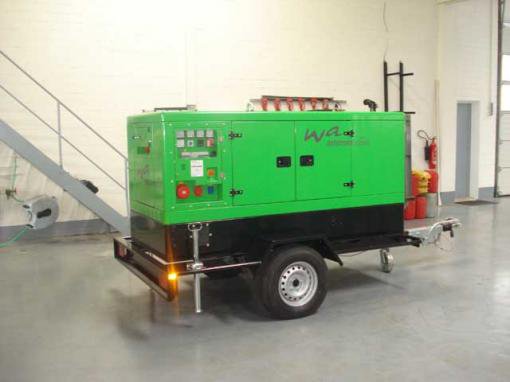
Deutz
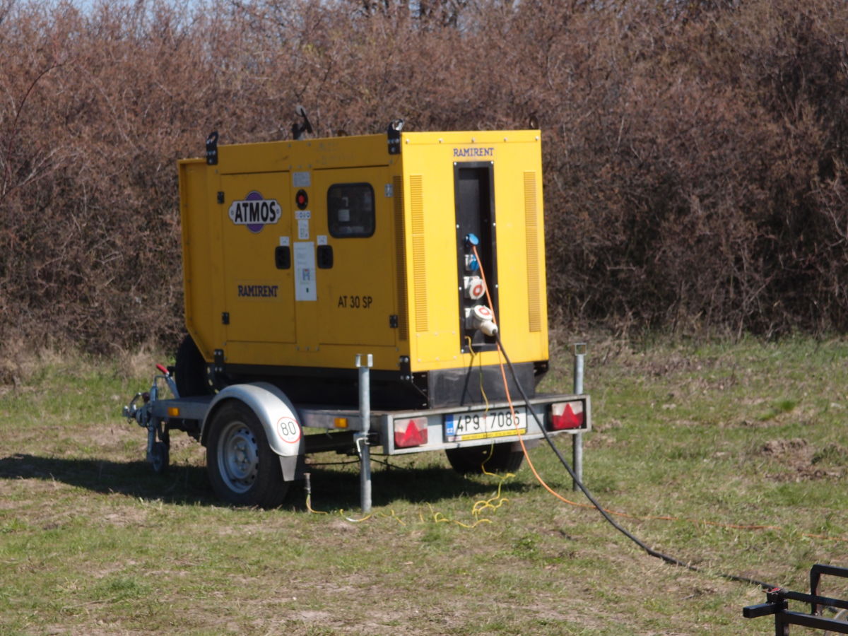
Atmos
A smaller generator (20 kVA) can be used for small dipoles in more resisitive areas.
If the current gets too high, the TXM-22 can limit the output current to prevent the generator to be overpowered.
You also may rent a generator from a construction company. Most construction companies use this kind or generators in order to have electricity at their site.
Example Injection Point
There are three simple rules only:
SAFE
a little DEEP
WET
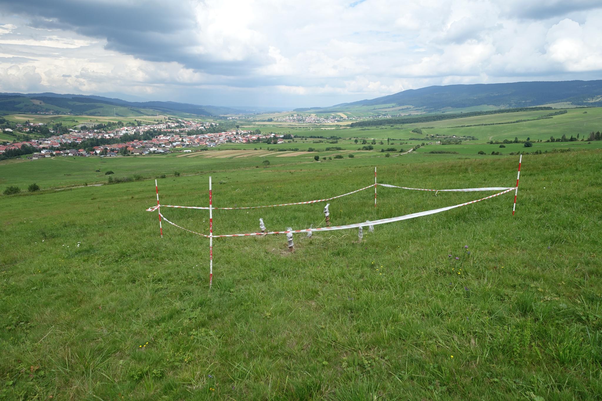
Each line and each electrode needs a guard. You must be able to shut down the transmitter immediately in case someone is going to touch the lines or injection points.
The electrode guards will be connected by walki-talki to the transmitter operator.
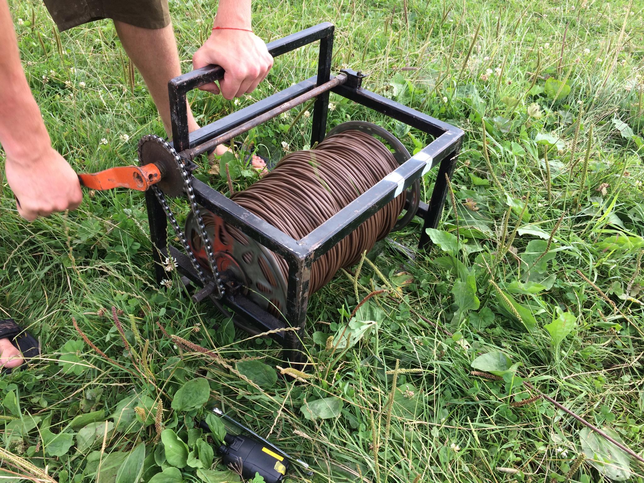
For 600m to 800m per dipole a 6 mm2 cable is good.
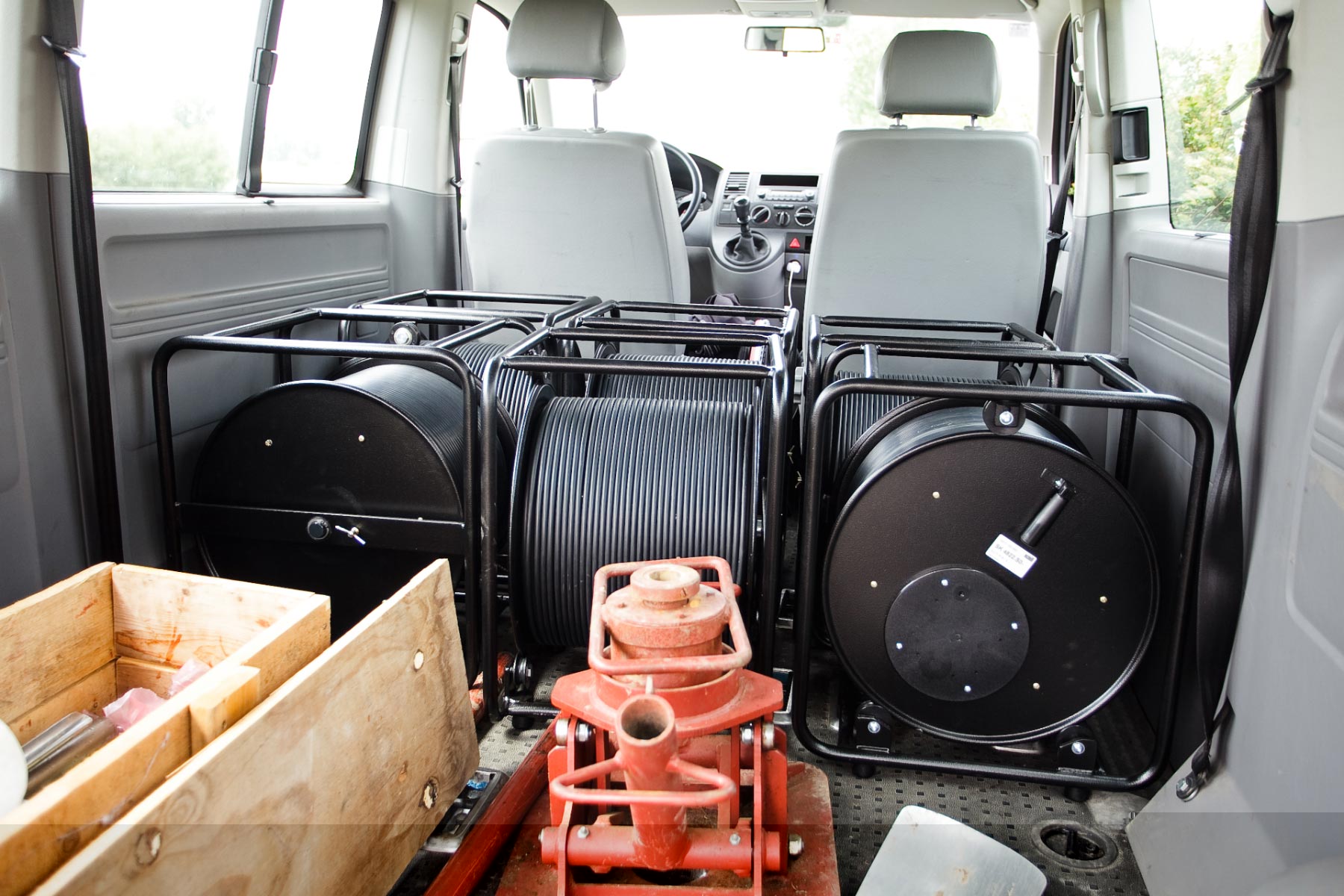
For higher security standards you take a double shielded cable
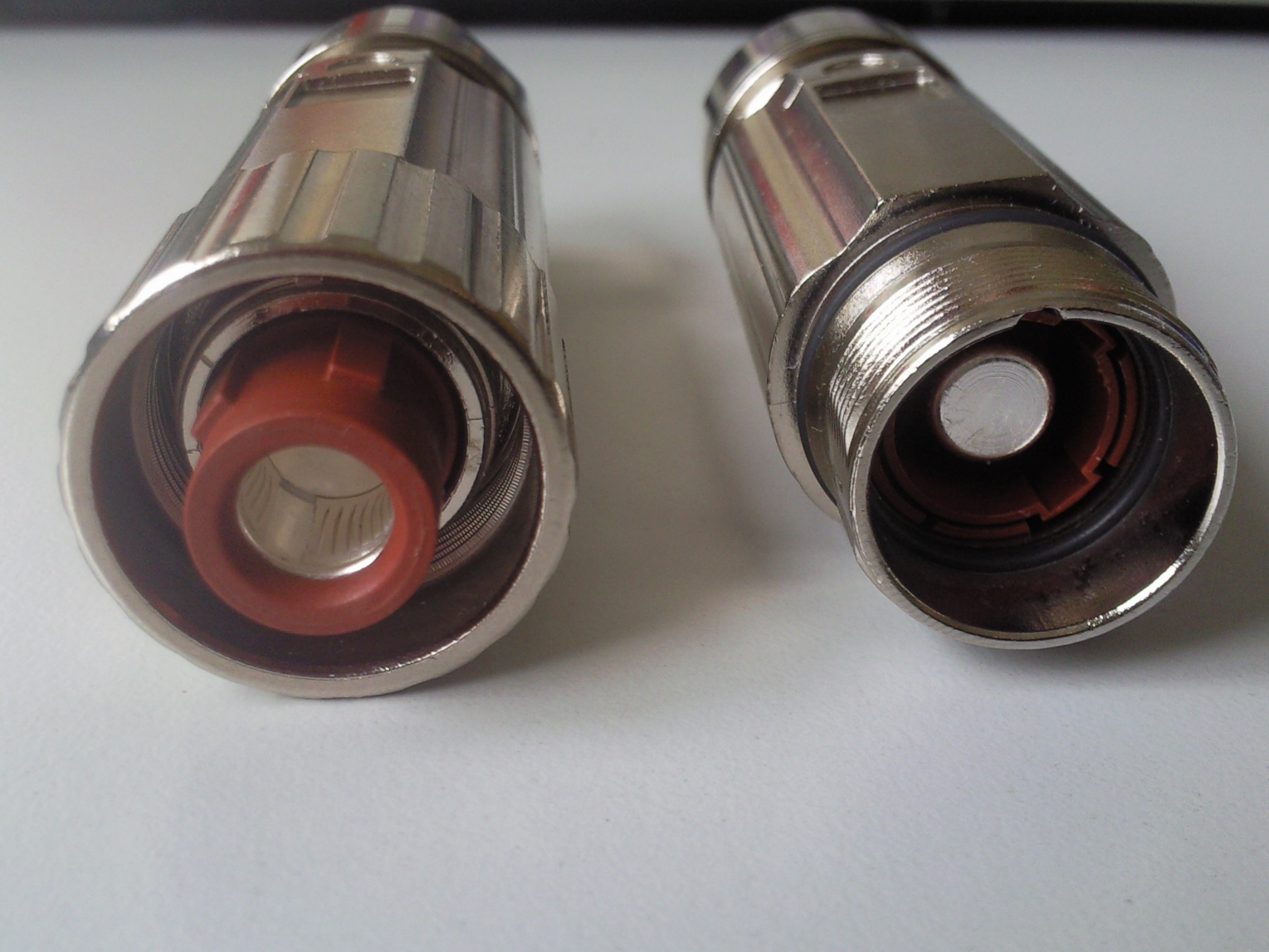
and insulated cable connectors.
There are several possibilities for the electrodes. The cheapest is to buy used drillers
The pits can be opened with a motor driller.
and finally put in by hand.
Example Setup by GEOTEM
A video committed by our partner GEOTEM shows a setup as airborne view
Safety and Mounting Instructions
Please download Safety and Mounting Instructions TXM-22-TXB-08.pdf
Environmental
In case the item is no longer needed, please dispose it according to the local regulations for electronic waste.
Dispose items only at qualified places, not in your household waste.

WEEE Reg. DE 25690185