atsfilter
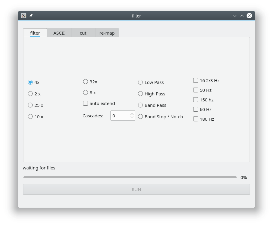
The default filter is 4x decimation. And the default spacing of frequencies is 16x.
By filtering each recording with 4x you get a continuous set of bands with 4x spacing - that is the idea ([How long do I have to record?](https://training.geo-metronix.de/FAQ_MT/FAQ_MT.html#how-long-do-i-have-to-record)
The drag & drop scans xml files recursive: you can drag & and drop several measdirs or even the complete site. Sure: for cutting you drop only one xml file (mostly).
The major purpose is to down filter the timeseries. By filtering you get lower sampling frequencies (lower bands). Theoretically you achieve the similar result by increasing the FFT … but not the same result. A FIR filter (finite impulse response) in time domain ist not the same like a “longer FFT”.
Filtering
filter tab
the default filter 4x is already checked.
If you have recorded for a longer time, go to the center to the Cascades scroll box and select, how many times the timerseries shall be filtered again.
- Options:
auto extend: filters down to a reasonable size
Low Pass …
High Pass …
Band pass …
The notch filters can be combined in case, for example 16 2/3 & 50 & 150 Hz. DO NOT USE THEM in case you want to process the data for MT later; the only possible usage is for display data in your publication. <br> The filtering is done in the time domain. But it is similar to a large window FFT with removing the desired frequencies. You may sometimes see differcences in processing the data with/without filtering; but this may be related to the settings of your processing. If you take large FFT windows and small Parzen windows the results between filtered and non filtered processing converge. <br> Another typical mistake is to evaluate frequencies too close to the sample rate. If you take a sampling rate of 256 Hz the evaluation of 64 Hz data is sportive. ProcMT takes 64 Hz already as corner frequency.

The 16 2/3 Hz 50 Hz / 150 Hz as well as the 60 Hz / 180 Hz filters can be combined.
The INPUT will not be deleted. In case of multiple filtering, temporary directories will appear shortly.
You identify the new directories by their date: the filter always has to shift by 1 s (or more for lower sampling rates); so using 50 & 150 Hz notch gives a 2 seconds shifted start time.
You may want to delete the source directories manually! (You have a copy of the originals see also notes ).
Default Filtering
ASCII
(click video to full screen)
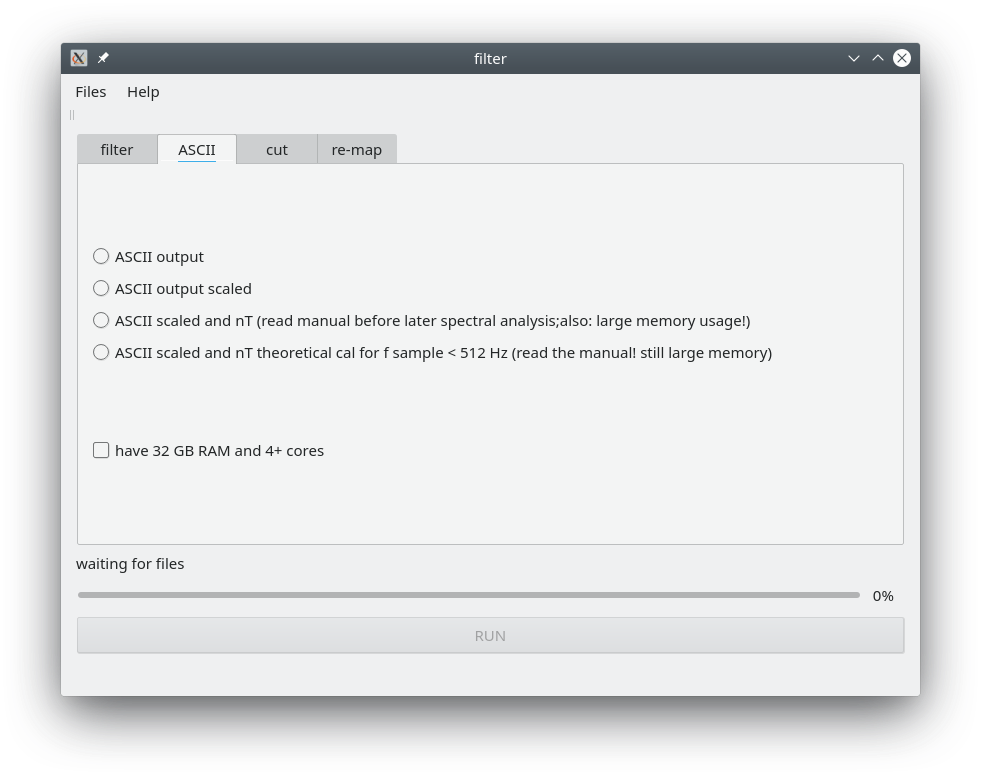
You can export to ASCII with following options:
Options:
ASCII output -> saves data as mV
ASCII output scaled -> scales E to mV/km -> that is the option you want
ASCII output scaled and nT -> tries! to convert data to mV (E) and nT (H)
ASCII output scaled and nT -> tries! to convert data to mV (E) and nT (H) using theoretical transfer function only
When using the theoretical function only - atsfilter will nevertheless load the calibration for f_sample > 512 Hz in order to avoid calibration errors.
WARNING 1
For the data in nT a full FFT inversion of ALL data is made. The FFT uses “zero padding” in order to have 22values (513 values will become 1024 values).
Having 50 MB ats data we get 100MB of doubles in RAM, padded to 200 MB.
The frequency, amplitude and phase values will also have 200 MB of size; that makes 800MB. Plus temporary storage we get 1.2 GB out of 50 MB of data!
The computation time takes very long; when you have not enough memory you computer will -> swap -> freeze -> dead
On some computers the GUI may freeze - but the software still runs (check with your system load). That may be caused by 100% workload.
WARNING 2
A FFT over 100,000 data points is NOT the same like N FTTs with 1024 point over 100,000 data points.
The detrend is NOT the same. So when sections are compared you get NOT the same result and the timeseries are looking different.
Also the spectra are not the same! For the professional timeseries analysis you may use a detrend and a Hanning window in order to avoid
a mapping of the window length (1024) into the spectral domain as sinc function.
Some virtual machines (VM) may break down early; also writing to the local drive via “network” may cause trouble.
The GUI seems to be not responding when the FFTs are calculated - please be patient
Conclusion
In case you know what you are doing, conversion is fine (display timeseries data).
If you compare with fluxgate data: cut the timeseries data into that segment you really want to compare.
If you want to use the inverted data for spectral processing or even magnetotelluric data … you may run into trouble.

Example: dropping folders:
Band Stop Filter
Important: Band stop filtering (notch filter) does not really improve the MT result.
During the MT processing you go to the spectral domain and simply avoid to 50 Hz or 150 Hz as target frequencies.
(click video to full screen)
Cutting
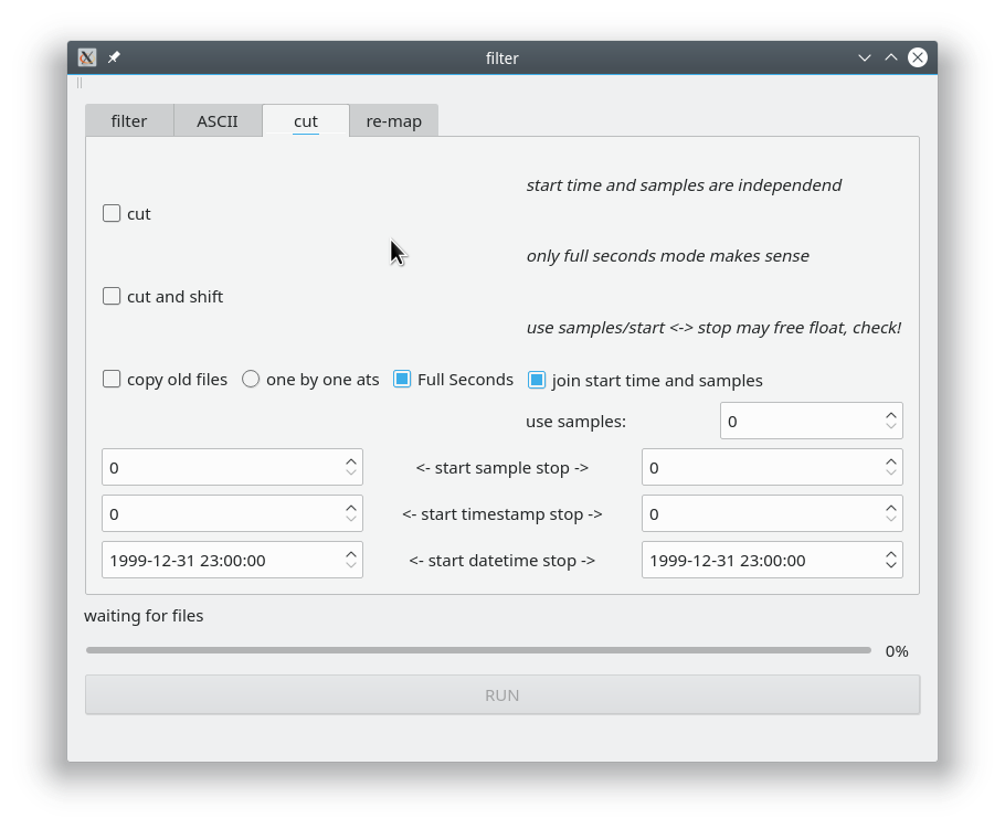
Cutting allows you to modify the the recording duration. This can be useful if you know that on the last day for example the E field was chopped of and this data is for ever useless.

Options:
cut : cuts from given start (time or sample) to given stop (time or sample)
cut and shift : … not implemented yet
copy old files If “copy old files” is checked (“cut should be activated automatically”) you can drag & drop old files from ADU-06 and ADU-07. Take always a set of 5 files.
The procedure is quite straight forward - it will not repair any awkward settings; chopper will be set automatically.one by one ats : indicates that time series will not down filtered while cutting (default)
Full seconds : if NOT checked you may be able to cut 6 samples from a 1024 Hz time series - otherwise counter will jump by 1024 (default)
join start time and samples : try to cut and stay GPS synced
re-map
First acknowledge that your data may be inconsistent - for whatever reason; and you have made already a backup.
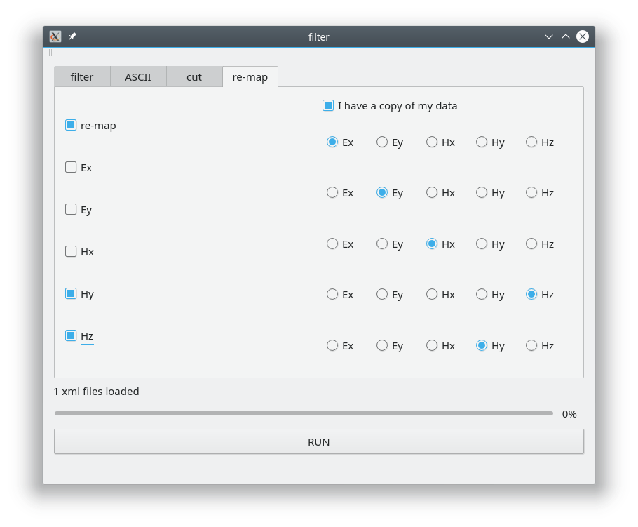
What is does:
Drag & Drop the XML file on top.
In the ats header (ref: ats header ) uiChanNo and achChanType will be changed.
Additionally the filename will be changed. Example Hy -> Hx
3 -> 2; Hy -> Hx; 203_V01_C03_R000_THy_BL_8H.ats -> 203_V01_C03_R000_THy_BL_8H.ats
Additionally the XML file has to be re-written (re-write the <ATSWriter> part and swapping the <calibration_sensors part>).
That are at least the <ATSWriter> section and the <calibration_sensors> section. Other parts remain untouched
Attention in case of a 5 channel file, you can not re-map a single channel logically! Also you can not create a new channel.
So it is simply spoken only possible to “swap” existing channels.

As you can see, Hy and Hz are checked and the button-matrix shows the desired action. You can drop a complete site in case ALL are 5 channels (or 4 and so on).
A sign reversal is NOT applied (dos not make West to East).
following options are available from a command line or (e.g. PHP) script in case XML files are selected (not ats files):
-filter 4x [or 2x, 4x, 8x, 10x, 25x, 32x]
-notch 50 [or 16_23, 50, 150, 50_150, 16_23_50_150, 60, 180, 60_180] where as 16_23 is 16 2/3 (railway frequency)
-ascii scaled [or raw, scaled, nt, nt_theo]
-gui false [true]
files (measdoc files)
Since the measdoc (like 216_2018-04-20_11-57-13_2018-04-23_07-58-02_R000_16H.xml) indicates all what is need you can use (for example) a recursive PHP script in order to
find which files you want to work on.
You can load many measdocs ath the same time.
If -gui true the gui will be called and you continue to work there.
Exmaple: atsfilter -ascii scaled -gui false meas_2018-04-20_11-57-13/216_2018-04-20_11-57-13_2018-04-23_07-58-02_R000_16H.xml meas_2018-04-20_12-00-00/216_2018-04-20_12-00-00_2018-04-24_07-58-02_R000_8H.xml
Script interface
notes
In the “old days” band-pass and notch filtering was used BEACAUSE the number of bits (e.g.14 or 16) where to small to digitize the MT signal including spikes (outliers).
You always (including today) you use a low pass filter which cuts of at (or before) the Nyquist frequency.
If you sample with 4 kHz the low pass filter must suppress all above 4 kHz (or better 3 kHz).
In theory you can calculate a FFT up to 2 kHz now (sampling theorem). For better resolution however you go up to 1 kHz or 512 Hz. In this case you are away from the filter influence
(modern delta-sigma ADC (analogue digital converter) sample at a MHz, so the low pass filter is actually higher). For the expert: with coils and fluxgate this is easy. But for the electric field we a coupled
to the ground (contact resistivity) - which is a non constant system. Therefore the ADU switches additional “radio filters” to compensate that.
In the old days additional analogue high pass and low pass filters where switched (signal conditioning) in order to keep the signal range small (max/min). Behind these filters
gains (analogue amplifier) were switched to feed the ADC into the optimum range. Especially you want to avoid over powering the ADC because the ADC has a relaxation time: that is the time he goes
back to normal operation.
What is normally not mentioned: all these filters have a) transfer function and b) a relaxation time. a) can be neglected in case your interpretation frequencies are far away from the filter’s corner frequencies.
b) however is a tragedy. If a spike (impulse) hits the filter, the filter smoothes the spike down to a long slope (where the data is ruined).
That is why the ADU systems to not use one of these filters.
The solution came with the new 24 bit and 32 bit ADCs. The max/min range is so high that the analogue filter conditioning is not needed anymore.
Removing the 50 / 60 Hz is cosmetics today. Only if the processing is not well conditioned (FFT, Parzen radius) you get influence from the powerline frequencies.