ADU Manual
Manual for ADU-10e and ADU-11e data loggers, referred as ADU.
ADU-10e switches the chopper on @ 512 Hz “classic”
ADU-11e switches the chopper on @ 1024 Hz
Also follow the Quick Notes for some tweaks.
Hence: ADU-11e sets chopper on for 1024 Hz by default (because it is the lowest sampling rate).
Safety Notes
The ADU-10e and ADU-11e are data loggers for geophysical applications. They digitize and record data from electric and magnetic field sensors. They may only be used for this purpose. Any usage apart from this application is not covered by this manual and must be avoided.
IF you have read the safety notes, you can jump to the Introduction sections of this manual.
For learning LM/ / MT / AMT visit metronix Training.
Technical data is summarized for the ADU-10e and the ADU-11e in their respective overview documents.
Used symbols
The following symbols are used in this manual:
Symbol |
Text |
|---|---|
|
Information Important information and notes. |
|
Caution! Non-observance may result in severe property damages. |
|
DANGER! Non-observance may result in property damages and in personal injuries. |
|
Electric Shock! Risk of electric shock. |
|
Grounding Symbol System needs to be grounded. |


General Notes
In case of damage resulting from non-compliance with the safety notes in this manual, metronix Messgeraete und Elektronik GmbH will not assume any liability.
Warning
Before using the system, please read the safety notes and the manual carefully.
If the documentation in the language at hand is not understood accurately, please contact and inform your supplier. Sound and safe operation of the instrument requires proper and professional transportation, storage, mechanical installation, and project planning – with a consideration of the risks as well as the protective and emergency measures – plus the proper and professional electrical installation, operation, and maintenance of the devices.
Only trained and qualified personnel is authorised to handle electrical devices and systems:
Trained and qualified personnel
in the sense of this product manual or the safety notes on the product itself are persons who are sufficiently familiar with the project, the setup, assembly, commissioning and operation of the product as well as all warnings and precautions as per the instructions in this manual and who are sufficiently qualified in their field of expertise:
Education and instruction concerning the standards and accident prevention regulations for the application, or authorization to switch devices/systems on and off and to ground them as per the standards of safety engineering and to efficiently label them as per the job demands.
Education and instruction as per the standards of safety engineering regarding the maintenance and use of adequate safety equipment.
First aid training.
The following notes must be read prior to the initial operation of the system to prevent personal injuries and/or property damages:
|
These safety notes must be complied with at all times. |
|---|---|
|
Do not try to install or commission the ADU before carefully reading all safety notes contained in this document. These safety instructions and all other user notes must be read prior to any work with the ADU. |
|
In case you do not have any user notes for the ADU, please contact your sales representative. Immediately demand these documents to be sent to the person responsible for the safe operation of the ADU. |
|
If you sell, rent and/or otherwise make this device available to others, these safety notes must also be included. |
|
The user must not open the ADU for safety and warranty reasons. |
|
Professional site layout and survey planning is a perquisite for sound operation of the ADU! |
|
DANGER! Inappropriate handling of the ADU and non-compliance with the warnings as well as inappropriate intervention in the safety features may result in property damage, personal injuries and electric shock. |
|---|
EMC
The ADU system applies to class A of the DIN EN IEC 61000-6-4 2020-09 (commercial / industrial environment). As such it is not meant to be used in class B environment (home use).
Danger
DANGER! If the ADU is used during thunderstorms it can happen that a direct lightning strike hits a connection cable especially an electric field cable. This can destroy the system. If the ADU is operated during such conditions personal injury and even death of the operating person can occur. Operation during thunderstorms is not allowed.
Safety Notes
General Safety Notes
|
Caution! The ADU corresponds to IP 6 degree of protection as well as pollution degree 8. Make sure that the environment corresponds to this degree of protection and pollution degree (IP68). |
|---|---|
|
Caution! Only use replacement parts and accessories approved by the manufacturer. |
|
Information The safety rules and regulations of the country in which the device will be operated must be complied with. |
|
Caution! The environment conditions defined in the product documentation must be kept. Safety-critical applications are not allowed, unless specifically approved by the manufacturer. |
|
Information For notes on installation corresponding to EMC, please refer to chapter 8. The compliance with the limits required by national regulations is the responsibility of the manufacturer of the machine or system. |
|
Caution! The technical data and the connection and installation conditions for the ADU are to be found in this product manual and must be met. |
|
DANGER! The general setup and safety regulations for work on power installations (for example DIN, VDE, EN, IEC or other national and international regulations) must be complied with. Non-compliance may result in death, personal injury or serious property damages. |

|
Information Without claiming completeness, the following regulations and others apply: |
|
|---|---|---|
EN55011:2009 +A1:2010 |
Industrial, scientific and medical (ISM) radio-frequency equipment – Electromagnetic disturbance characteristics – Limits and methods of measurement. |
|
EN61000-4-6-2014 |
Electromagnetic compatibility (EMC) - Part 4-6: Testing and measurement techniques - Immunity to conducted disturbances, induced by radio-frequency fields (IEC 61000-4-6:2013); German version EN 61000-4-6:2014 |
|
EN61000-4-8-2010 |
Electromagnetic compatibility (EMC) - Part 4-8: Testing and measurement techniques - Power frequency magnetic field immunity test (IEC 61000-4-8:2009); German version EN 61000-4-8:2010 |
Safety Notes for Assembly and Maintenance
The appropriate DIN, VDE, EN and IEC regulations as well as all national and local safety regulations and rules for the prevention of accidents apply for the assembly and maintenance of the system. The plant engineer or the operator is responsible for compliance with these regulations:
|
Caution! The ADU must only be operated, maintained and/or repaired by personnel trained and qualified for working on or with the system. |
|---|
Note
Prevention of accidents, injuries and/or damages
|
Take care of heavy components, like MFS-06e/07e sensors. Getting hit by these components may cause serious injuries. |
|---|---|
|
Keep the electrical equipment voltage-free disconnecting the battery and protect it from being switched on, in the case of: Maintenance and repair work Cleaning long machine shutdowns |
|
Prior to carrying out maintenance work make sure that the power supply has been turned off and locked, batteries have been disconnected. |
|
The external supply battery may push very big currents, if being shorted. |
|
Be careful during the assembly. During the assembly and also later during operation of the ADU, make sure to prevent from being flooded by water (e.g. during very heavy rain fall). Additionally take care that the maximum ambient temperature of 50°C is not exceeded, e.g. by protecting the ADU against direct impact from the sun. |
|
Electronic devices are never fail-safe. It is the user’s responsibility, in the case an electrical device fails, to make sure the system is transferred into a secure state. |
Protection Against Contact With Electrical Parts
The appropriate DIN, VDE, EN and IEC regulations as well as all national and local safety regulations and rules for the prevention of accidents apply for the assembly and maintenance of the system. The survey manager is responsible for compliance with these regulations:
|
DANGER! Risk of electric shock! The external supply battery may push very big currents, if being shorted. |
|---|
Protection against Electrical Shock By Means Of Protective Extra-low Voltage (PELV)
All connections and terminals of the ADU are at a level of +/- 12V DC and therefore are protective extra-low voltage.
It is designed safe from contact in correspondence with the following standards:
International: IEC 60364-4-41
European countries within the EU: EN 61800-5-1
|
DANGER! High electrical voltages due to wrong connections must be avoided! Danger to life, risk of injury due to electrical shock! |
|---|
Only devices, electrical components and wires with a protective extra low voltage (PELV) may be connected to connectors and terminals with voltages between 0 to 50 Volts.
Protection against Dangerous Movements
Not applicable as the ADU does not contains any moving parts.
Protection against Contact with Hot/cold Parts
|
DANGER! In case the ADU is operated during very hot/cold weather the housing parts of the ADU may get very hot/cold. In this case the risk of injury is given, if the system is touched. |
|---|

Protection during Handling and Assembly
Handling and assembly of certain parts and components in an unsuitable manner may under adverse conditions cause injuries.
|
DANGER! Risk of injury due to improper handling! Personal injury due to pinching, shearing, cutting, crushing! |
|---|
The following general safety notes apply:
|
Comply with the general setup and safety regulations on handling and assembly. |
|---|---|
|
Use suitable assembly and transportation devices. |
|
Prevent incarcerations and contusions by means of suitable protective measures. |
|
Use suitable tools only. If specified, use special tools. |
|
Use lifting devices and tools appropriately. |
|
If necessary, use suitable protective equipment (for example goggles, protective footwear, protective gloves). |
|
Do not stand underneath hanging loads. |
|
Remove leaking liquids on the floor immediately to prevent slipping. |
Trademarks
Android™ is a trademark of “Google Inc”
Windows™ is a trademark of “Microsoft Corporation”
Linux™ is a trademark of “The Linux Foundation”
Introduction
Performance Characteristics
The ADU (Analog Digital Unit) systems are the core units of the metronix multi-channel Geophysical Measurement Systems GMS-10 / GMS-11. It is the result of more than 50 years of metronix´ experience in the design and manufacture of electromagnetic geophysical instruments.
The ADU is a 10e:5, 11e: 8 channel logger used for broad band MT and AMT. It allows to set-up for standard 5-channel MT sites, using 2 E-fields along with 3 H-fields connected to MFS-XXe sensors and/or additional connection of FGS-XXe or SHFT-XXe sensors for either high frequency of very low frequency soundings.
Each ADU can be operated as a stand-alone system, in a network using standard Local Area Network (LAN), or as part of an array, in which each unit is synchronized by its built-in GNSS (GPS / Galileo / BeiDou) controlled precision clock. An access via a WiFi access point is available, too.
The ADU electronics is housed in a water proof, ruggedized alloy case. In spite of the small size, it contains the complete circuitry for analog signal conditioning, A/D conversion and data storage. A very precise satellite controlled time base allows to synchronize multiple units.
Data is stored on a SD flash card with a capacity of up to 2TByte (11e: 128GByte by default, 10e: 32GByte by default and also max). Data also can be stored on an external USB device which is connected to the ADU.
Either the single ADU or a complete network of several ADUs can be controlled via a standard PC using a standard web-browser.
All metronix magnetometers like MFS-XXe, FGS-XXe and SHFT‑XXe can be connected to the ADU. It is also possible to connect magnetometers from other companies on option.
The system provides a high degree of flexibility for various sensor setups. Due to its scalable and modular concept it can grow with the requirements of the user. The low number of different components also simplifies the spare part requirement.
Front Panel
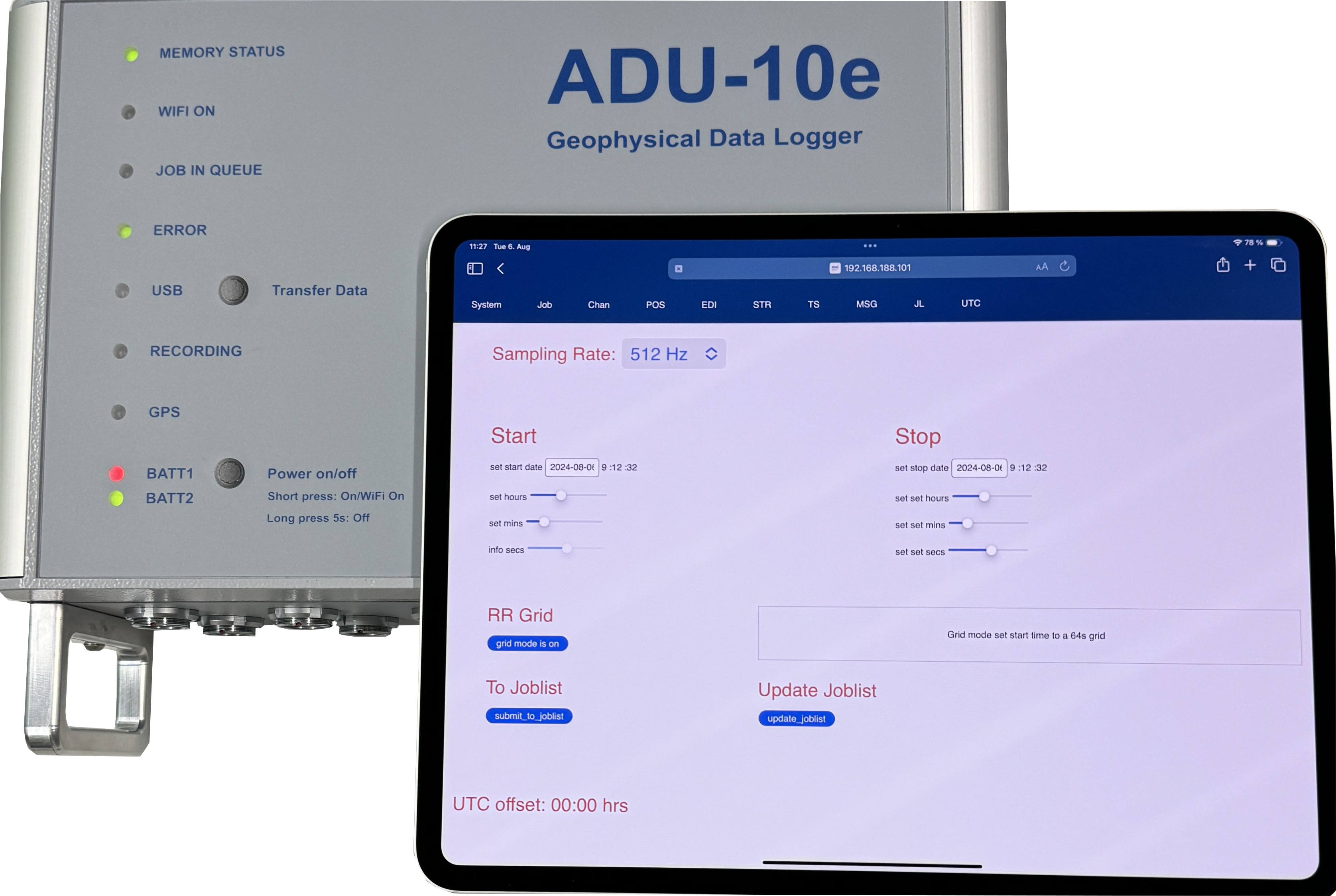
ADU Front Panel
Buttons:
Button |
Function |
|---|---|
Power on/off |
This button is used to switch the system on. Additionally, if the system is already powered, a short press will activate the WiFi, if it is switched off. A long press >10s will trigger the system shutdown procedure which needs to be confirmed by another long press >10s |
Transfer Data |
By the use of this button a transfer of all internal measurement data to a externally connected USB mass storage device can be started. The USB LED will indicate the result of the procedure. During transfer it will be green yellow red yellow in case copy is successfully. It will end up blinking red in case the copy procedure failed. |
Battery Status LEDs BATT1 and BATT2:
Status |
Description |
|---|---|
|
OFF battery is not connected or not detected |
|
GREEN battery voltage is GOOD (>13V), battery is fully charged |
|
YELLOW battery voltage is FAIR (>10V … < 13V), battery is OK |
|
RED battery voltage is BAD (<10V), battery is bad and should be replaced. Otherwise the system may be shut down. |
GPS:
Status |
Description |
|---|---|
|
OFF No Fix – now sync to GPS because no GPS antenna connected or no free view to the sky. |
|
Blinking: |
|
GREEN G4Fix acquired – system is fully synchronized to GPS time and hence to all other systems in the array that also acquired a G4Fix. |
Recording:
Status |
Description |
|---|---|
|
OFF No recording is active – system is idle |
|
RED recording is active – data is acquired |
USB:
Status |
Description |
|---|---|
|
OFF No USB mass storage device connected |
|
GREEN USB mass storage device connected, but not in use. |
|
YELLOW USB mass storage device connected and mounted to the system (hence in use, but no data is actually written to it) |
|
RED USB mass storage is in use and data is written to it. |
|
RED – blinking USB copy process that was started via Transfer button failed. |
ERROR:
Status |
Description |
|---|---|
|
OFF no selftest yet executed |
|
GREEN selftest finished successfully |
|
YELLOW selftest finished with warning check the selftest results page in Webinterface. System likely is OK to record data, but e.g. the probe resistance on e-field may be big hinting to badly connected electrodes. |
|
RED selftest finished with critical error definitely check the selftest results page in Webinterface as something is severely wrong and it is very likely to produce bad data without fixing the problem (e.g. a bad h-field sensor was detected). |
|
BLINKING selftest is still active. According to colour the result so far is either |
JOB IN QUEUE:
Status |
Description |
|---|---|
|
OFF No job scheduled for future |
|
GREEN At least 1 job is scheduled to be started in future |
WiFi ON:
Status |
Description |
|---|---|
|
OFF WiFi is switched off – no connection to ADU is possible |
|
GREEN blinking WiFi is active – ADU is visible as access point with SSID “ADU11E_SSS” with SSS being its serial number |
|
GREEN At least 1 client is actually connected via WiFi to ADU system |
|
Information Note that the WiFi will be switched off automatically after 15 minutes of no active connection in order to save power. |
MEMORY STATUS:
Status |
Description |
|---|---|
|
GREEN internal data storage is at least 80% free |
|
YELLOW less than 20%, but more than 5 MB are still available on internal data storage |
|
RED less than 5 MB are free on internal storage. A running job may be stopped soon because of no free disk space being available. |
|
RED blinking An error occurred with internal data storage. Check the internal SD card. During this condition no data can be acquired. |
Connectors
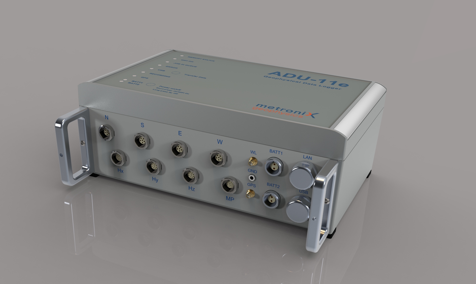
ADU Connectors
E-Field Connectors N/S/E/W for standard and buffered E-field cable
These four terminals are used to connect the standard or the buffered E-field cables. The plugs on the E-field cable have 6 pins. The center pin 6 is the pin where the standard E-field cable has to be connected to. In a typical arrangement the ADU is located in the center of the two E-field lines. Plug-in the cable connector in a way that the red dots match on plug and socket and push the plug in until it clicks.
Polarity
EX: NORTH = Plus, SOUTH = Minus
EY: EAST = Plus, WEST = Minus
H-Field Connectors Hx/Hy/Hz for Magnetic Field Sensors
These three terminals are used to connect the magnetic field sensors. The plugs on the H-field cable have 10 pins. The center pin 10 is the pin where the MFS-XXe sensor has to be connected to. Plug-in the cable connector in a way that the red dots match on plug and socket and push the plug in until it clicks.
The polarity of the magnetic fields is defined in a way that a positive flux change in the positive sensor direction will cause a positive output voltage on the A/D converter.
The positive sensor direction of all sensors is given when the sensor for example is showing NORTH. In case of the MFS-XXe sensors at this moment the cable ended side is SOUTH.
Multi-Purpose Connector for additional sensors
This terminal can be used to connect additional sensors like FGS-XXe or SHFT-XXe. The plugs on the cable have 10 pins. The center pin 10 is the pin where the sensor has to be connected to. Plug-in the cable connector in a way that the red dots match on plug and socket and push the plug in until it clicks.
GND Socket
This socket is used to connect the grounding rod or electrode with the ADU. The grounding can be done by a steel rod or an electrode. Grounding should be done closely to the ADU.
Grounding
Danger
YOU MUST GROUND THE SYSTEM!
NO GROUNDING - NO DATA!
The electric field es referenced to the ground. If the system is not grounded, the electric field is “floating”.
For the grounding you can use a standard 4.2 mm banana plug. The grounding can be done by a steel rod or an electrode. Grounding should be done closely to the ADU. The grounding rod should be driven into the ground. Take care the after e.g. hammering the rod into the ground, it is in good contact with the soil and not wobbling.
One steel rod with grounding cable is included in the delivery.
Note
Take the same electrode type for grounding as used for the electric field sensors to ensure consistent measurements. So steel rod, if you use steel rod for E-field, or non polarizable electrode, if you use non polarizable electrodes for E-field.
Antenna socket for GPS antenna
The GPS antenna is connected via this SMA socket. Any SMA compatible 3.3V active GPS antenna can be used.
WITHOUT GPS the system can not sync to time and position. It will work OK for a single site station, but there may be time shifts to other systems in a array.
Also the frequency stability of the system will be worse without GPS, which may cause problems for long term recordings.
One GPS antenna is included in the delivery.
Antenna socket for WiFi antenna
The WiFi antenna is connected via this SMA socket.
Many standard WiFi antennas with SMA connector can be used.
A fitting WiFi antenna is part of the delivery of the ADU system.
Battery Connectors
The ADU is equipped with 2 battery sockets. You can connect a 12V battery or two batteries in parallel for extended operation time.
Two Battery cables are part of the delivery of the ADU system.
The input voltage is 12 V nominal; the allowed voltage spans from 10.5V to max. 16V.
The inputs are protected against:
Wrong polarity
Overvoltage
Short circuit
Note
Batteries are not always reliable. Always connect two batteries in parallel, that makes it more fail safe.
Check the current drawn from each battery, and replace the battery with the lower current first.
Network socket
The ADU system can be connected to a network via the RJ45 socket. The ADU provides a Gigabit Ethernet connection on this socket.
The IP address be default is 192.168.100.SSS with SSS being the serial number of the system.
USB socket
USB devices can be connected via this USB-A type socket. Any connected USB device will be available inside the Linux system of the ADU.
In most cases USB mass storage devices are connected to this socket to either copy data from the system or start pre-defined joblists that are stored on the USB device.
External USB WiFi dongles are supported, too, if the internal WiFi is not sufficient. Note that only devices with known chipsets, such as RT8192CU, RT8188EU, … are supported.
Bootup Process
When the ADU system is powered on by pressing the Power on/off button, the internal Linux system will be started. During this process all hardware components are initialized and a selftest is executed. The selftest checks all important hardware components of the system and reports any errors or warnings via the ERROR LED.
If the system does not boot:
Check the battery voltage
Check the connections
Check the polarity of the batteries (+ / - correctly connected?)
Battery cable faulty?
CONNECT THE SENSORS AND E-FIELD FIRST
The system performs a self-test, checks the sensors and electric field connections before starting normal operation. Gains and sensor settings are determined during this process.
If you made changes to the sensor connections or the E-field connections, please make sure to power cycle the system to have the self-test performed again with the new connections.
Especially when you use the mobile Web-Interface the App deeply relies that the system is in a well conditioned state after boot-up.
The “Self-test” ends as soon as the “Error” LED on the ADU Front-panel stops blinking (with green, yellow or red).
ETHERNET CONNECTION
The laptop is connected to the ADU with the network cable. As a network cable you may use any standard Cat5e or better network cable with RJ45 plugs. One end of this cable is connected to the socket labeled „NET“, the other end is connected to the Ethernet socket of the laptop computer.
If the communication is ok and after having entered the proper network address which is written on the sticker on the front cover into your browser you will be able to contact the ADU. We recommend to book-mark the ADU´s address in your browser.
The IP address is written on the sticker on front of ADU case. By default it is:
192.168.100.NNN with NNN being the serial number of the ADU system.
The ADU does not have a DHCP server, so you need to set a static IP address on your laptop in the same subnet. For example, if the ADU has the IP address 192.168.100.123, you could set your laptop to 192.168.100.1 and the network mask to 255.255.255.0. NEVER set the laptop IP address to the same IP address as the ADU, otherwise you will have an IP conflict and no communication will be possible.
Note: you can use could use old Cat5e cables for the connection, but we recommend to use Cat7 cables for better performance and reliability. The maximum length of the network cable is 100m.
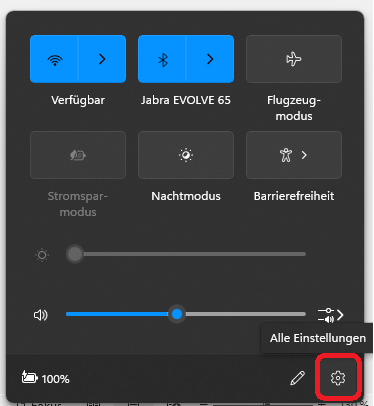
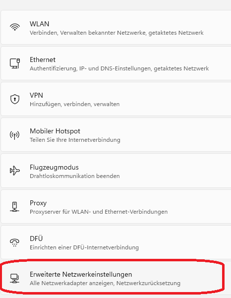
On a (German, but you can adapt it) laptop with Windows 11 you can set the static IP address as follows:
step |
picture |
|---|---|
Open the Network Manager |
< |
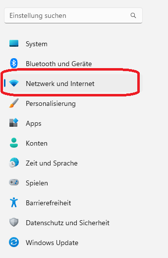
Click on “Network and Internet” |
< |
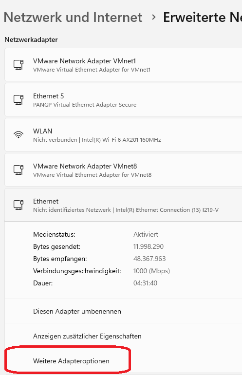
Select “Advanced Settings” |
< |
Select the Ethernet interface |
|
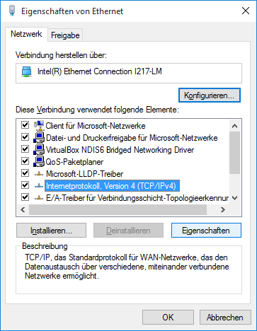
Select TCP/IPv4 and click on “Properties” |
|
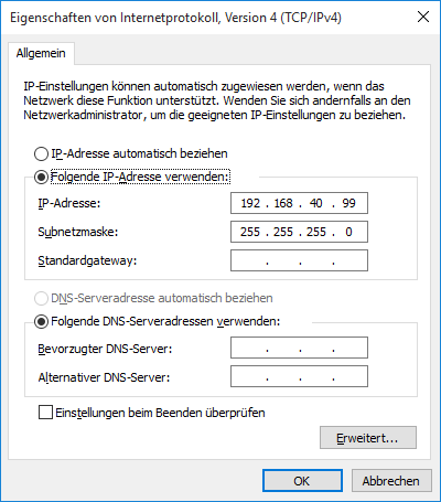
Click on “Edit” |
|
Note
Again: if the ADU has 192.168.100.5 as IP address, set your laptop to 192.168.100.1 and the network mask to 255.255.255.0 for example. NEVER set the laptop IP address to the same IP address as the ADU, otherwise you will have an IP conflict and no communication will be possible.
You can use your console and type ping 192.168.100.5 (in this example) to check if the connection is ok (there should be NO LOSS). If you get a response, you can open the web interface by typing https://192.168.100.5 in your browser.
ADU Network Settings
ADU IN YOUR LOCAL NETWORK
The ADU has - as mentioned before - a fixed IP address like 192.168.100.22 .
Warning
WARNING! If you connect the ADU to your local network with cable it can BLOCK YOUR NETWORK!
Devices which have obtained an IP address from your local DHCP with the same IP address can be invisible now. Take care.
Note
ADDITIONALLY! The ADU obtains a DHCP address from your local network, in case the DHCP server accepts!
in /lib/systemd/network/ you can find the file 10-eth0.network which contains the following lines:
[Match]
Name=eth0

[Network]
DHCP=ipv4
Address=192.168.100.1/24

[DHCP]
# When CriticalConnection is applied to networkd, the IP address will not
# change after this service was reloaded. Just reboot the system.
CriticalConnection=true
Comment out the line Address=192.168.100.1/24 if you want the ADU to obtain an IP address from your local DHCP server ONLY.
YOU WILL NOT BE ABLE TO CONTACT THE ADU VIA 192.168.100.SSS ANYMORE! DURING FIELD WORK!!
CHANGE to 192.168.100.SSS (SSS= serial number of the ADU) to get back to the old settings.
Important
TRAP!!! NO LEADING ZERO IN IP ADDRESS! In case your serial is 25, you must use 192.168.100.25 and not 192.168.100.025.
Important
IMPORTANT! The WiFi access point of the ADU is always active. Connect in emergency to the ADU via WiFi and change the network settings of the ADU to fit your local network.
WiFi CONNECTION
WiFi is more easy:
Press the Power on/off button for a short time to activate the WiFi. The WiFi LED will start blinking green.
On your laptop, search for WiFi networks and connect to the network with the SSID “ADU11E_SSS” with SSS being the serial number of the ADU system. The password is written on the sticker on the front cover of the ADU.
After connecting to the WiFi network, open your browser and type https://192.168.100.SSS with SSS being the serial number of the ADU system. You should now be able to access the web interface of the ADU system.
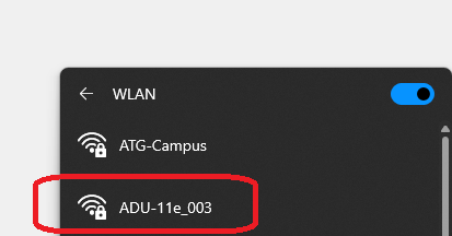
ADU SSID
Note
Again: shortly press the Power on/off button to activate the WiFi. If you wait too long you may believe the WiFi disappeared, but it is just switched off to save power.
Poor WiFi Connection
Tablets and mobile phones often report “limited connectivity” or start to re-connect to another WiFi network.
Reason: they secretly check for Google or Apple servers to check if the internet connection is ok. If they do not get a response, they assume the WiFi is not working and start to search for another WiFi network.
Setting up the WiFi connection
In case your IP address of the WiFi does not fit to the serial number:
Go to the /home/scripts/startW-Lan.sh script and change the line (example for serial #25):
C_IP_ADDRESS=192.168.110.25
C_ESSID=ADU11E_025
Pre-Measurement Checks
Hint
The mobile Web-Interface has a complete different design philosophy: in 95% of all cases the self-test and sensor checks are ok. You must use the E-series sensors with detection. If the self-test is “yellow”, check contact resistivity, grounding and anisotropy of the site.
The mobile Web-Interface is a “off you go!” interface.
Once the ADU has booted up and the self-test has finished (indicated by GPS and Battery LEDs stop blinking), the following checks need to be performed:
Check Self-test Results
The self-test results need to be checked, too. This is done the easiest way by checking the “Error” LED on frontpanel:
Status |
Description |
|---|---|
|
GREEN: selftest finished successfully It is save to continue and start with measurements. |
|
YELLOW: selftest finished with warning check the selftest results page in Webinterface. System likely is OK to record data, but e.g. the probe resistance on e-field may be big hinting to badly connected electrodes. |
|
RED: selftest finished with critical error definitely check the selftest results page in Webinterface as something is severely wrong and it is very likely to produce bad data without fixing the problem (e.g. a bad h-field sensor was detected). |
In most cases they will be OK (LED = green). In case of warnings (LED = yellow) or critical errors (LED = red) the self-test results MUST be checked before the start of the measurement. This can be done in the following ways.
Quick Notes
SCRIPTS HOME
in /home/scripts are system scripts ONLY for the ADU; nothing to do for you here!
SCRIPTS MTDATA
in /mtdata/Scripts is more or less only CopyToUSB.sh of importance. But you can add more.
$1
$2
$3
$4
$5
$6
$7
$8
In the “Processing Queue” execShellScript -> atswriter /mtdata/Scripts/CopyToUSB.sh mind the full path!
Moving Mode
Inside /mtdata/Joblists/ToggleGPSDynaMode for example you have
 ADUConf/
 ToggleGPSDynaMode/
so inside the folder:
cp -a * /mtdata/AutoStartJoblist
now the moving mode is executed after boot. You can keep the ADU connected to the battery while moving to the next station. Use detect sensors in order to make sure that nothing is scrambled up. AND execute sensor test to check gains and contact resistances.
AFTER that you can use use auto gain. This is a must. And since you know that the E-field is te trouble maker, you definitively don’t want to skip this step.
You only can have one joblist here!
A professional Job-List
under manuals.geo-metronix.de go to
DOWNLOADS -> software -> latest -> JobLists -> 32_8
copy the content of 32768Hz_stl (start later) : these are the directories ADUConf and Jobs to the ROOT of your USB stick!
This can be a vfat (FAT32 or exFAT) or ext4 formatted USB stick.
The old xml loader does not recognize all, but that is fine so far. You edit the job, and off you go.
This example job is a 32 kHz job, 32 seconds every 2 minutes. And continuously 8 kHz.
You adjust some settings , and off you go.
        stateDiagram-v2
    [*] --> Ready
    Ready: Ready / New Session
    Ready --> Edit_Job : insert USB
    Edit_Job: Edit Job<br>(view jobtable)
    Edit_Job --> efield : Positions
    efield: Edit E-field <br> (sensor positions)
    efield --> autogain : after boot
    efield --> detect_Sensors : continued
    detect_Sensors: detect sensors (3 min)<br> (sensor positions)
    detect_Sensors --> sensor_test : resistance
    sensor_test: sensor test<br> (selftest config)
    sensor_test -->  autogain
    autogain: use autogain <br> (start job)
    autogain --> recording : start measurement
    recording: recording
    recording --> [*]